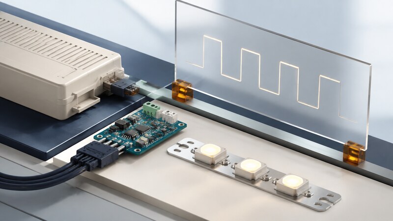
An LED driver controls the electrical current delivered to one or more light-emitting diodes. A useful design maintains the intended operating conditions as supply voltage, LED forward voltage, and temperature change.
A simple indicator can use a series resistor when its current variation is acceptable. Lighting applications often need regulated current, dimming, and defined fault behavior. Begin with the LED arrangement and operating range, then choose the driver topology.
Match the topology to the voltage range
| Method | Useful situation | Main consideration |
|---|---|---|
| Series resistor | Small indicators with tolerable current variation. | Current depends on supply and LED forward voltage. |
| Linear current regulator | Supply stays above the LED string voltage with sufficient headroom. | Excess voltage becomes heat. |
| Buck converter | Supply remains sufficiently above the required output. | Switching behavior, minimum headroom, and current ripple. |
| Boost converter | Output needs to exceed the supply. | Open-load voltage behavior and the permitted input/output range. |
| Buck-boost converter | Input can be above or below the string voltage. | Complexity and efficiency across the complete range. |
Check the chosen part's actual operating envelope. A topology name does not guarantee regulation at every input voltage or dimming level. Series-connected LEDs carry the same current; parallel strings may require separate current control to prevent unequal sharing.
Worked example: account for the missing watt
The 3.15 W delivered to the LEDs is not all visible light; the LEDs also generate heat. Both the driver and LEDs need thermal paths consistent with their ratings and environment. A small package's electrical capability does not establish adequate cooling on an arbitrary board.
Recalculate at the supply extremes and across the LED forward-voltage range. Confirm the regulator retains enough headroom at minimum supply and maximum string voltage. At maximum supply and minimum string voltage, check the additional dissipation.
Choose dimming behavior deliberately
Analog dimming changes the regulated current. Pulse-width modulation (PWM) changes the proportion of time the LEDs are driven. A driver may support either approach or a combination. Check current accuracy and behavior at the low end of the intended brightness range.
Texas Instruments' explanation of LED dimming methods describes analog adjustment and PWM control. Their effects should be evaluated with the particular driver and LED assembly.
For an ideal 350 mA current pulse at 25% duty cycle, average LED current is 87.5 mA. Real behavior depends on rise time, fall time, minimum pulse width, and regulation settling. Perceived brightness is not a simple linear measure of average current, and cameras can reveal modulation that a person does not notice.
Define the state during startup, communication loss, and firmware reset. A control interface that receives a brightness command needs a specified default when that command is absent.
Check the operating corners and fault response
Measure LED current and ripple using an appropriate method, then compare them with the intended settings. Measure input power and output power at the same operating point if estimating efficiency. Keep temperature and dimming conditions with the record.
Review the manufacturer's defined behavior for open and shorted strings, undervoltage, and overtemperature. Do not assume that a protection feature eliminates every system-level failure mode. Follow the device's evaluation procedure when examining fault behavior.
For a low-voltage prototype, begin with a documented evaluation circuit and the specified supply conditions. Inspect the layout guidance for current loops, sensing, grounding, and heat spreading. Switching designs are sensitive to physical implementation as well as component values.
Build a short selection record
Record minimum and maximum input voltage, LED configuration, current range, dimming requirements, ambient conditions, and available board area. Compare candidates against the same requirements rather than selecting from a maximum-current headline.
AI can help extract these fields from supplied datasheets and identify missing information. Require a source section for each value, and distinguish typical performance from guaranteed limits. Check any generated component calculation against the manufacturer's design equations.
Can a microcontroller power the LEDs directly?
Its output ratings and the complete load decide that. A small indicator is different from a lighting string. Use the processor as a control source when a separate driver is required, and verify signal-level compatibility.
The electronic circuits page works through a smaller resistor-driven indicator example.