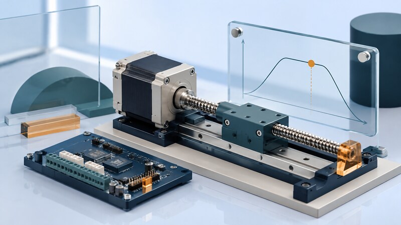
Motion control electronics translate a requested movement into electrical drive signals for a motor. The complete system also includes mechanics, a motion profile, position references, and sometimes feedback that reveals whether the movement actually happened.
Start with the load and the required motion. Travel, speed, acceleration, repeatability, and stopping behavior influence the motor, transmission, driver, and controller together. A driver's microstep setting or a motor's headline torque cannot establish the accuracy of the assembled mechanism.
Choose the motor and control approach together
| Approach | Reason to consider it | Question to resolve |
|---|---|---|
| Open-loop stepper | Repeatable commanded increments with relatively simple control. | Is adequate torque available throughout the speed and load range? |
| Stepper with feedback | Detection and correction of some position errors. | Where is position measured, and what faults can still go unseen? |
| Servo system | Feedback-controlled position, speed, or torque. | How will the loop be tuned and verified with the actual mechanics? |
| Brushed or brushless DC drive | Continuous rotation or controlled actuation. | Which sensing and control are needed for the required behavior? |
A servo describes a feedback-controlled system, not one exclusive motor construction. Compare complete configurations. Torque measured while a motor holds still should not be assumed available at operating speed.
Worked example: command resolution versus accuracy
That is commanded resolution. Backlash, screw error, compliance, load, motor behavior, and missed steps affect actual position. A 2.5-micrometer command increment is not evidence of 2.5-micrometer positioning accuracy.
Analog Devices' discussion of microstepping explains why finer electrical subdivisions do not remove mechanical and motor accuracy limits. Verify travel with an appropriate measurement method in both directions and under representative loads.
Give the driver an achievable trajectory
A motion planner defines the requested speed and acceleration over time. Asking a stationary mechanism to jump immediately to its final pulse rate can exceed available torque. Use a profile appropriate to the inertia, transmission, and operating range, then verify it experimentally.
The motor driver regulates winding current or applies the drive waveform. Check its supply range, current-setting convention, thermal requirements, and pulse timing. Peak and RMS current figures are not interchangeable without understanding the waveform and the manufacturer's definition.
Firmware should handle direction changes, enable timing, and interruptions deliberately. Hardware timers can generate repeatable pulse timing while software coordinates the trajectory. Confirm the resulting signals on the real controller rather than relying on a requested frequency alone.
Diagnose the symptom at the right layer
| Symptom | Possible explanations | Evidence to collect |
|---|---|---|
| Loses position during acceleration | Excessive load demand, inadequate current, or drive faults. | Pulse timing, current configuration, fault records, and measured motion. |
| Different endpoint depending on direction | Backlash, compliance, or reference behavior. | Repeated forward and reverse approaches under similar load. |
| Vibration in part of the speed range | Mechanical resonance or drive-current behavior. | Speed-dependent observations and mechanical inspection. |
| Unexpected homing result | Reference sensing or detection settings do not match the application. | Repeated homing results across relevant speed, load, and temperature. |
Sensorless stall detection estimates behavior from electrical measurements. Its usefulness depends on the motor, speed, load, and configured method. It is not automatically equivalent to an independent position sensor or a safety limit.
An encoder on the motor can confirm shaft movement while missing downstream backlash or a slipping coupling. Choose the feedback location according to the error the system must detect.
Validate movement and recovery as a system
Measure repeatability, absolute positioning error, and direction-dependent behavior separately. Test normal starts and stops, loss of a reference signal, and restart after an interruption. Establish whether the position is still known or a new referencing operation is required.
Keep automated movement within the application's defined limits and recovery procedure. Review mechanical hazards and stopping requirements as part of the machine integration. Ordinary motion firmware should not be assumed to provide an independent protective function.
AI-assisted analysis can organize logs or check unit conversions. Ask it to separate commanded and observed position, identify missing measurements, and test the pulse calculation above. Use its hypotheses to plan measurements; a plausible explanation for a stall is not a confirmed diagnosis.
For the controller software, see embedded processors and firmware testing.