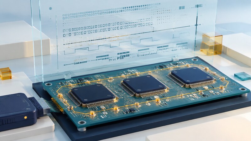
Boundary scan uses test circuitry built into compatible integrated circuits to control or observe selected device pins. It can help test board connections that are difficult to reach with physical probes, including connections beneath large packages.
Its value is precise but bounded: a test can establish evidence about the connections and behaviors it exercises. Passing a scan-chain check is not proof that the board's application works, that every solder joint is sound, or that high-speed signals meet their requirements.
Distinguish test access from the job being performed
JTAG commonly refers to the test access architecture associated with IEEE 1149.1. Its Test Access Port uses clock, mode-control, data-in, and data-out signals; some implementations also expose a test reset. Device-specific documentation determines the available registers and instructions.
The same access mechanism may support boundary scan, processor debugging, or programming. A connector labeled JTAG does not establish the board's structural test coverage. XJTAG's introductory explanation describes these related uses and the role of boundary cells.
| Test | Evidence it can provide | What it does not establish alone |
|---|---|---|
| Scan-chain integrity | The expected devices can be accessed through the configured chain. | All connections outside that chain are correct. |
| Interconnect test | Selected driven and observed nets match expected behavior. | Untested nets or high-speed signal quality. |
| Peripheral exercise | A modeled peripheral responds through accessible signals. | Every operating mode of that peripheral. |
| Functional test | The configured board performs a defined application task. | Complete structural fault coverage. |
Prepare the board description before the vectors
The test setup needs accurate connectivity information and the boundary-scan description for each relevant device. A Boundary Scan Description Language (BSDL) file describes capabilities such as pin mapping, boundary cells, and supported instructions. Match it to the actual device and package.
Record chain order, supply domains, test-access voltage, reset behavior, and required configuration states. Identify devices that may drive shared nets. The test plan must account for output enables and inactive states so two outputs are not instructed to oppose each other.
Keep the board netlist, BSDL files, fixture configuration, and test software revision together. A changed pin assignment or device package can invalidate a previously useful test without making the script itself look different.
Worked example: observe a two-line connection
These are conceptual patterns, not ready-to-run vectors. Actual test generation must account for the rest of the board, device behavior, and possible contention. Compare the result with the schematic and other measurements before replacing a component.
Read coverage with its denominator
A coverage percentage is meaningful only when the report defines what is counted. Nets, pins, modeled faults, and components are different denominators. Ask which items were excluded, which faults are detectable, and which require another test method.
Some connections cannot be independently driven or observed. Analog behavior and normal operating-speed performance may need separate instrumentation. Mixed-signal boundary-scan capabilities require specific device support; ordinary digital test access does not automatically provide analog measurement.
Classify outcomes as passed, failed, untested, or inconclusive where appropriate. A test skipped because a chain could not be accessed should not be included among passing tests. Combine structural results with functional tests and relevant physical inspection.
Use a repeatable failure investigation
- Confirm the board and test configuration revisions match.
- Check chain access and required supply and reset states.
- Locate the failing net or observation in the schematic.
- Review expected drive, observation, and output-enable behavior.
- Use an independent measurement or inspection to distinguish likely causes.
- Repeat the relevant tests after correction and retain the result.
AI can help organize a failure report and map referenced nets to supplied design records. Ask it to cite each mapping and keep observed failures separate from proposed causes. Generated vectors need the same engineering review as manually written tests.
When is boundary scan most useful?
When a board has compatible devices, difficult physical access, and a clear set of structural questions. Plan that access during device and system design, then maintain the test as the board evolves.