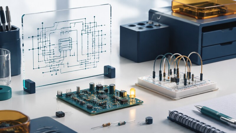
An electronic circuit connects components so that electrical signals and energy perform a useful job. Designing one means translating a requirement into connections, component values, and a physical implementation that behaves as intended.
AI can help explain a datasheet, draft a simulation, or review a parts list. The useful workflow still moves through calculation, inspection, and measurement. A convincing schematic needs the right pin assignments, operating conditions, and component models before it can become a dependable prototype.
Define the circuit before selecting parts
Write down the power source, input signal, required output, operating environment, and acceptable error. For a sensor interface, include the signal range and bandwidth. For an indicator, specify brightness needs and current. For a battery device, define active and standby behavior.
Divide a larger design into power, input, processing, and output blocks. Label supply rails, signal direction, and ground references. Check whether connected devices use compatible voltage levels; matching connector shapes or interface names does not establish electrical compatibility.
| Artifact | Purpose | Check |
|---|---|---|
| Schematic | Describe components and electrical connections. | Pin numbers, supply connections, and signal paths. |
| Datasheet | Define a particular component and its operating limits. | Exact part suffix, package, and test conditions. |
| Simulation | Predict behavior under stated assumptions. | Model applicability and omitted effects. |
| PCB layout | Realize connections in copper and physical parts. | Footprints, return paths, spacing, and assembly access. |
Worked example: an LED and a series resistor
This is an illustrative low-voltage calculation, not a complete component specification. LED forward voltage changes with current and temperature. Check the highest supply voltage, lowest forward voltage, resistor tolerance, and the selected parts' ratings. A microcontroller output also has pin and package current limits; it is not an ideal 5 V source.
Measure the voltage across the resistor and infer current from I = V / R. Compare the result with the prediction and the actual resistance. For regulated lighting and larger loads, see the separate LED driver page.
Simulate the question you need answered
Use a circuit simulator to explore operating points, transients, frequency response, or tolerance effects. Start with a case you can calculate by hand. If the simulated LED circuit disagrees dramatically with the example, inspect units, polarity, model parameters, and supply connections before adding complexity.
A model may omit thermal behavior, wiring parasitics, startup conditions, or protective circuitry. A simulated success establishes behavior within the model's assumptions. It does not verify a connector footprint or an incorrectly assembled board.
KiCad's getting-started guide covers the schematic-to-board workflow, including electrical and design rule checks. Use the documentation matching your installed version when following interface instructions.
Build and measure in small steps
For an introductory project, use a low-voltage, current-limited DC supply and simple loads. Inspect the unpowered assembly for reversed components and unintended connections. Verify the supply rails before adding a processor or connecting an expensive sensor.
A solderless breadboard is useful for many slow, simple experiments. Long jumper wires and contact parasitics make it a poor substitute for a carefully laid out high-speed or precision circuit. Choose a prototype method appropriate to the signal and current.
Record expected voltages, measured voltages, and instrument settings. Change one thing at a time while diagnosing a fault. Before ordering a PCB, compare symbol pins with footprint pads and the component package drawing, then review the fabrication outputs.
Give AI evidence and a specific review task
Review this low-voltage indicator design using the attached component datasheets. Recalculate resistor current and dissipation across the stated tolerances. Identify unsupported assumptions, cite relevant datasheet sections, and list measurements that would test the design.
Ask for the reasoning and source behind a recommendation. Verify part numbers, pinouts, and package dimensions independently. Keep the schematic, bill of materials, simulation, and measurement notes under version control so changes remain explainable.
What makes a useful first project?
A small circuit with an observable result and a prediction you can check. An indicator, button input, or simple sensor interface can teach more than a complicated design whose behavior is difficult to isolate. Add firmware after the electrical interface is understood.