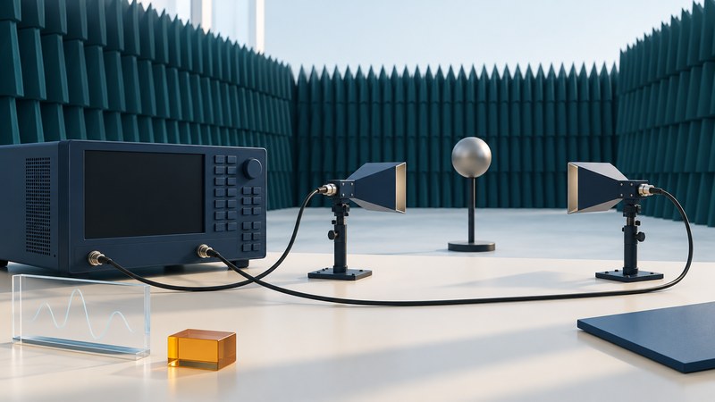
The economical radar measurement system is the one that answers a defined question with an adequate uncertainty and a manageable total cost. For antenna and radar cross-section work, the instrument is only one part of that system.
Begin with the measurement you need, then compare the fixtures, reference standards, environment, software and staff time required to obtain it. This guide is for planning laboratory measurements and discussing requirements with a qualified test facility.
Define the measurement before choosing equipment
| Question | Typical observation | What makes the result meaningful |
|---|---|---|
| How well is an antenna port matched? | Reflection coefficient at a defined electrical reference plane. | Calibration, connector condition, frequency range and fixture effects. |
| How does an antenna radiate in different directions? | Field amplitude and phase, or derived pattern/gain information. | Known geometry, polarization, reference response and appropriate range method. |
| How strongly does an object scatter toward a receiver? | A radar cross-section measurement for a specified configuration. | Frequency, illumination/viewing angles, polarization, background and a suitable reference. |
A good input match and a useful radiation pattern are separate properties. A network analyzer's S11 measurement describes reflection at a port; it does not by itself establish gain or a far-field pattern. Keysight's network-analyzer documentation distinguishes reflection and transmission measurements and explains the associated calibration settings.
Radar cross section (RCS) describes scattering for specified conditions, commonly expressed in square meters or in decibels relative to one square meter. An object's shape, orientation, material and the measurement frequency matter. Record those conditions with the result instead of treating a single RCS value as a universal property.
Plan the complete test system
A vector network analyzer can measure relative amplitude and phase and can form part of an antenna or scattering measurement system. It still needs the appropriate antennas, cables, positioning, references and processing. Keysight's historical PNA antenna/RCS white paper shows how instrument configuration and acquisition methods affect test time.
In 2003, SPC's Cheetah announcement described an instrumentation system built around Agilent PNA analyzers for antenna and RCS measurements. That example illustrates integration of a measurement chain. A dated product announcement supplies historical context; a present-day proposal needs its own configuration, uncertainty and cost evidence.
- Signal path: specify the frequency range, useful receiver sensitivity, required channels and polarization combinations.
- Geometry: document source, receiver, test object and positioner locations, including how angles and distances are established.
- Environment: characterize unwanted reflections, supports, leakage and background signals.
- Calibration and references: define the electrical reference plane and the additional reference measurements needed for the radiated quantity.
- Data: retain settings, calibration identity, raw observations, processing version and derived results together.
An electrical port calibration addresses errors within its defined measurement path. Converting free-space observations into a defensible antenna or RCS result adds its own geometry, reference and background requirements. Ask the facility to explain how it verifies the complete measurement, including the mounting fixture.
Trade cost against the uncertainty you can accept
A narrower intermediate-frequency bandwidth can reduce trace noise but lengthen a sweep; taking more frequency points also takes time. These tradeoffs are documented in the FieldFox network-analyzer guidance. Confirm their behavior on the actual instrument rather than borrowing a speed claim from another model.
Time-domain processing can help distinguish returns by delay, and gating can select a region of interest. The available frequency span, sampling and window affect what can be separated. Keysight's time-domain documentation explains resolution, range and gating. A gate is a processing choice to document and test; it does not remove the need to understand the background.
A published bistatic RCS test-method study offers an example of a lower-cost experimental arrangement using time gating and a reference configuration. Its particular geometry and targets define the result's scope. Use such research to formulate questions for a lab, rather than assuming the arrangement supports every object or frequency.
Compare purchase or rental with an outside test service using the same requirements. Count calibration, reference objects, cables and adapters, positioning, facilities, software licenses, training, setup time, analysis and repeat work. Reusing equipment can save money when its verified capabilities meet the requirement.
Worked example: scope changes the data volume
For a cost estimate, ask every supplier to quote the same measurement scope and deliverables. A cheaper quote may cover fewer angles, omit uncertainty reporting or require you to supply the fixtures. Make those differences explicit before comparing totals.
Write a requirements brief and an acceptance check
Download the plain-text measurement brief. Fill it in before requesting equipment or facility quotations.
- State the decision. Write what the result must let you accept, reject or compare. Name the quantity and units.
- Bound the test. Specify frequency, object size, geometry, angles, polarization and environmental conditions.
- Set the evidence requirement. Agree an uncertainty target and how it will be evaluated with appropriate references and repeat observations.
- Request a representative demonstration. Include background/reference observations and an independently understood check where feasible. Retain the settings and processing used.
- Specify delivery. Require sufficient raw data, metadata and analysis detail to understand the result, along with limitations and exceptions.
Use the laboratory's approved procedures for RF operation, positioning and equipment protection. A planning illustration or general explanation cannot specify safe power levels, exposure distances or an approved assembly for an unknown setup.