Compare the space the job actually needs
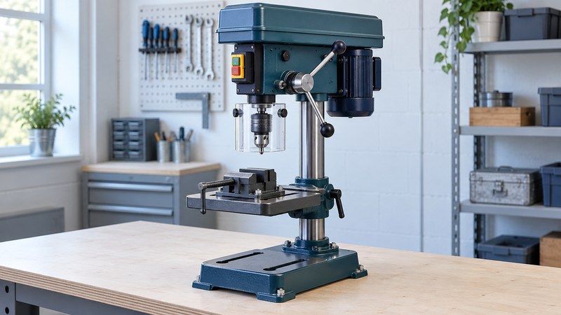
A drill press supports controlled vertical drilling and repeatable positioning, but the nameplate size alone does not show whether a job fits. Start with a sample workpiece, the required hole and the complete fixture. A bench model saves floor space only if its supporting bench is stable and has enough room around it.
| Specification | What it describes | Check at the job |
|---|---|---|
| Swing | Conventionally twice the spindle-to-column distance | Can the hole center reach the intended position? |
| Spindle travel | Available downward movement of the spindle | Can the required depth be reached in the planned setup? |
| Chuck capacity | The shank sizes the chuck accepts | Does the selected bit fit within machine limits? |
| Vertical clearance | Space for the bit, work and fixture | Include the vise, backing board and bit length. |
| Speed range | Available spindle speeds | Does it include the bit maker’s recommended range? |
List the materials and cutters you intend to use, not just the largest hole. A wood boring bit and a metal twist drill can need very different setups. Confirm that the machine is approved for the material and operation; a drill press is not automatically a milling machine.
Make the workholding plan first
CCOHS drill-press guidance calls for clamps or a drill vise to prevent the work from spinning. Secure the vise or fixture to the table as required; simply putting a heavy vise beneath the chuck is insufficient. Clamp round stock in a suitable fixture rather than trying to stop it rolling by hand.
Mount the machine securely using its instructions. Support long pieces so they cannot tip or lever the work loose. Check that the table is locked and that the intended drilling path clears the table, clamps and fixture. Use a suitable sacrificial backing piece where the operation calls for one.
Before running, remove the chuck key, close the guards and establish the stop control. Wear eye protection, contain long hair and remove loose clothing and jewelry. Do not wear gloves near the rotating spindle. Stop the machine fully before measuring or adjusting; remove chips with a brush or suitable vacuum after stopping, not with bare hands.
Select speed for the cutter and material
Use the bit maker’s guidance for the cutter diameter and material, together with the machine’s available speeds and operating limits. There is no single useful RPM for “wood” or “metal.” The JET JDP-17 manual (PDF) includes a speed chart by bit type, size and material, illustrating why several inputs are needed.
For a belt-driven machine, disconnect power before opening the cover or changing belts, then follow its tensioning and cover-closing procedure. Variable-speed mechanisms have their own adjustment rules. Record the selected speed and the source of that choice so it can be checked later.
Apply feed appropriate to the bit and material. Reduce feed near breakthrough as advised by CCOHS. If the cutter chatters, stalls or produces unexpected heat, stop and inspect the complete setup. Changing speed at random can hide a loose fixture or damaged cutter. Use lubricant only where appropriate for the material, tool and machine.
Set depth from a defined surface
The depth stop limits travel; it does not decide which part of a pointed hole counts as the required depth. Identify whether the drawing calls for overall tip depth or usable full-diameter depth. For a blind hole, leave the bottom thickness required by the design and the cutter geometry.
With power isolated, set the work surface as the reference using the machine’s depth-stop procedure. JET’s manual describes referencing the top of the work and locking the selected travel. Its control sequence is specific to that model. After setting your machine, drill a test piece of the same material and thickness, stop fully, and measure the actual result.
Check the first hole, then repeat deliberately
- Inspect the stopped test piece for diameter, location, depth, exit damage and fit with the intended mating part.
- If the result is wrong, isolate power and correct one identified cause: reference position, stop setting, work support or cutter selection.
- Retest after a change. A setup that produced a good hole before the table moved needs a new check.
- During a run, check representative parts and recheck after a bit or fixture change. Stop immediately for loosening work or abnormal movement.
For tear-out, inspect the backing arrangement and breakthrough feed. For inconsistent depths, inspect the reference surface, chips beneath the work and stop locking. For an oversized or visibly wandering hole, investigate cutter condition, work movement and chuck or spindle condition before continuing. Have mechanical faults serviced rather than compensating with hand pressure.
Keep a brief job record: machine, material, bit, speed source, reference face, fixture, stop setting and measured first-hole result. That record makes a later repeat job easier to reconstruct without treating an old setting as universally correct.
Choose your next guide
- Drill Bits — Check the material, hole shape and shank before choosing a bit.
- Locking Pliers — Choose locking-plier jaws and check how the work is held.
- Machine Tool Training — Compare supervised courses and practical skills assessment.
Browse drilling and holemaking or explore all 47 tool guides.