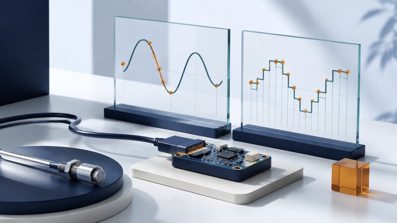
An analog-to-digital converter (ADC) represents an analog input with a digital code. It is the bridge between a physical signal and software that records, displays, or analyzes that signal.
The number of bits tells you how many codes are available. It does not establish the accuracy of the complete measurement. The sensor, input circuit, reference, timing, layout, and software interpretation all contribute to the result.
Read beyond the bit count
| Term | What it describes | Question to ask |
|---|---|---|
| Resolution | The number of available digital codes. | How large is one code step over the selected input span? |
| Sampling rate | How often conversions sample the signal. | What input bandwidth and timing does the application require? |
| Offset and gain error | Deviation from the expected transfer relationship. | Can calibration address the error over the needed conditions? |
| Noise and distortion | Variation and unwanted signal content. | What performance is specified at the operating rate and frequency? |
| Reference | The electrical scale used in conversion. | How stable and quiet is it under load and temperature changes? |
Texas Instruments' ADC training series covers converter architectures, sampling, noise, and signal-chain design. Consult the selected converter's transfer function and input requirements when applying these concepts.
Worked example: interpret a 12-bit code
Actual transfer functions can define transition locations and endpoint behavior differently. Use the datasheet's convention. Dividing by 4,095 maps the maximum code to 3.3 V, but that endpoint mapping should not be confused with the width of 4,096 equal intervals.
A 1% reference-scale error corresponds to about 16.5 mV at a 1.65 V reading, much larger than one nominal code step. Extra displayed decimal places do not remove that error. Preserve the raw code and reference configuration with the converted value.
Prevent ambiguity before the conversion
For a baseband signal, sampling must account for the highest frequency reaching the ADC, including unwanted content. A practical design uses an analog anti-alias filter and enough separation between the wanted band and the sampling limit for that filter to work.
As a simple illustration, a 700 Hz sine wave sampled at 1,000 samples per second can appear as a 300 Hz component. Once aliased, digital filtering cannot reliably identify which original frequency produced those samples.
Noise filtering and averaging have costs. Averaging suitable uncorrelated noise can stabilize a reading, but it reduces responsiveness and does not remove systematic offset or reference error. Record filtering and decimation so downstream analysis knows the effective bandwidth and delay.
Design the signal path around the converter
Check input range, common-mode limits, source impedance, acquisition time, and the required driver circuit. An ADC input may need to charge an internal sampling capacitor; a high-impedance source can fail to settle accurately before conversion.
Provide the reference and supply decoupling described by the manufacturer. Consider grounding and return-current paths. A high-resolution converter placed beside a noisy switching circuit needs more than a software average to achieve useful performance.
For multiplexed channels, account for settling after switching and associate each code with the correct channel. Preserve saturation, communication faults, and missing samples as explicit conditions rather than turning them into valid zero readings.
Validate the complete measurement
Apply known inputs within the permitted range and compare readings across several points, including the expected operating region. Record the test source's uncertainty and the instrument configuration. Repeated readings help characterize noise; several known levels help reveal offset, gain, and nonlinearity.
Repeat relevant checks across temperature, sampling rate, and channel sequence. A calibration made under one set of conditions may not cover another. Keep calibration coefficients and their provenance with the device configuration.
Review this synthetic ADC dataset and conversion formula. Check code range, units, reference scaling, timestamps, saturation, and missing samples. Separate observed noise from possible calibration error, and show the calculations behind each finding.
AI-assisted analysis is useful for plots and consistency checks. Verify scaling with a hand-worked case such as code 2,048 before interpreting patterns. A model cannot reconstruct information that was clipped, aliased, or never measured.
When should I choose an external ADC?
When the required input behavior, accuracy, channels, or sampling performance exceeds what the processor's built-in converter can provide. Compare the complete signal chain and integration effort, not bit count alone.