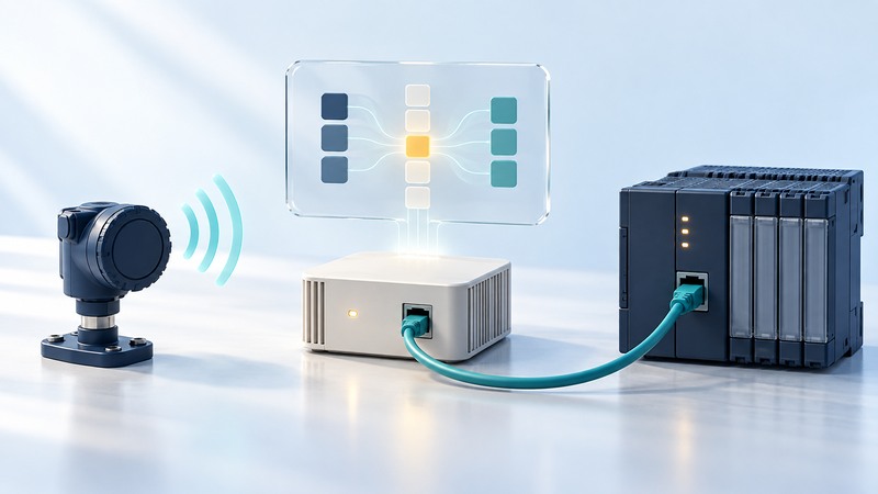
A Zigbee Ethernet gateway exposes selected wireless data or functions to an Ethernet-side application. Specify exactly what crosses that boundary: device identity, values, units, timestamps, commands and failure status. Prove the mapping on a bench before connecting it to an operational system.
This guide is for integrators planning a monitoring connection. You need the exact gateway and sensor manuals, supported firmware versions, an approved test network and a read-only test client. Keep operational writes and control changes within the site's engineering process.
Distinguish the three interfaces
The wireless side has device roles and application functions. The gateway translates or forwards supported data. The Ethernet side exposes a defined service, such as an API, message protocol or Modbus interface. An Ethernet connector alone does not specify which of those services exists.
For a concrete, documented architecture, ICP DAS's ZT-2570/ZT-2571 manual, version 1.5, describes transparent and gateway modes and Modbus RTU/TCP examples. It explicitly explains that the system carries application data rather than merging the two Ethernet LANs. Its addressing and device combinations belong to that product family; confirm support for your exact equipment before procurement.
That serial-data architecture differs from a gateway exposing native Zigbee sensor attributes. For either design, obtain evidence for the specific function you need. A supported radio protocol or successful join still leaves the application mapping to be verified. See Zigbee compatibility and network roles for the wireless-side questions.
Write a data contract
Scroll the table horizontally; keyboard users can focus it and use the arrow keys.
| Field | What to establish | How to check |
|---|---|---|
| Identity | Sensor identifier and Ethernet-side address/topic/register | Change one test input and observe only its expected record. |
| Value | Type, signedness, scale, unit and invalid-value convention | Compare known normal, boundary and invalid test values. |
| Time | Measurement time, receipt time and reporting interval | Introduce a bench delay and inspect the exposed timestamps. |
| Quality | How stale, unavailable or uncertain data is identified | Disconnect the test sensor and observe the agreed failure indication. |
| Recovery | Buffering, duplicates and reconnect behavior | Restore the connection and inspect ordering and original measurement times. |
For Modbus, record the function code, zero-based protocol address, register count and unit identifier where applicable. A manual's human-facing register number may use a different convention from a client's address field. Resolve the convention explicitly using a known value.
The Modbus Application Protocol Specification V1.1b3 defines data objects, addressing, function codes and exception responses. A device manual supplies the meaning of its individual registers. Multi-register values also require the device's word-order convention, while register values need the documented scale and unit.
Example: map a temperature without inventing a register
Use the editable gateway mapping record to replace every example field with the selected product's documented interface. If the device exposes no measurement timestamp or quality field, specify how the receiving application will detect stale data and what uncertainty remains.
Test from sensor to application
- Confirm exact models, firmware, compatible device functions and the gateway's supported operating mode.
- Configure the approved bench network and a single test sensor. Verify its identity, joining and expected reports using the manufacturer's tools.
- Read one documented value from the Ethernet side. Compare raw and scaled results with the sensor's own reading or a suitable test reference.
- Test a known negative or boundary value where the measurement supports it. This can reveal signedness and scale errors.
- Interrupt the sensor's reporting path and then the gateway's Ethernet connection in separate approved tests. Distinguish sensor silence, cached data, protocol exceptions and transport timeouts.
- Restore each path and verify reconnect behavior, duplicates, buffered records and application status. Record the observed recovery interval.
Keep polling consistent with the sensor's reporting behavior and gateway capacity. A sleeping sensor may report on its own schedule; faster polling of a cached gateway value does not produce newer measurements. Limit retries and outstanding requests according to the selected implementation.
Deploy a bounded, maintainable interface
Restrict gateway management and data access to the intended hosts and network segments. Confirm transport security in the actual protocol implementation; a protocol name alone does not establish authentication or encryption. Keep production writes disabled unless required and explicitly engineered.
Retain the complete mapping, manual revision, firmware, configuration backup and expected failure behavior. Re-run the bench cases after gateway, sensor or application changes. Use the monitoring-pilot guide to evaluate completeness and timeliness across the full deployment.