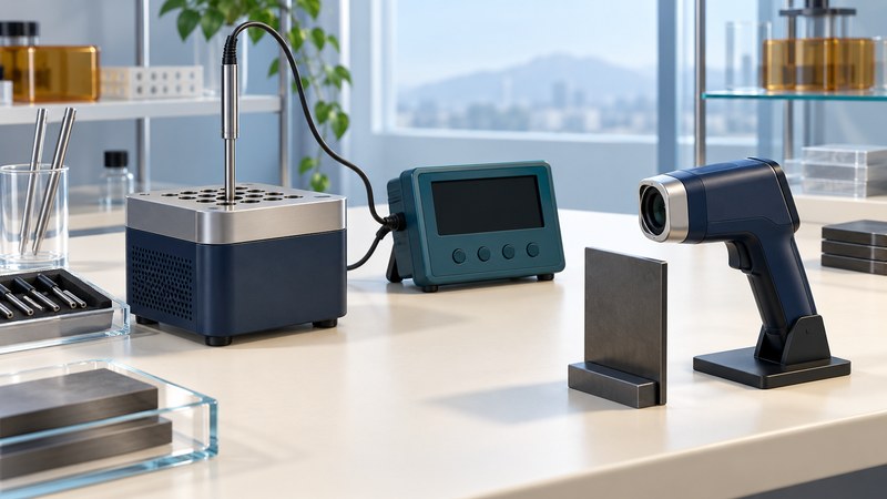
Choose a temperature instrument by defining what must be measured: a surface, a fluid, the air around a product, or the interior of a part. Then check whether the sensor, installation and readout can support the required decision. A precise display is useful only when its reading represents the intended location and time.
Describe the process decision
For a process engineer or maintenance technician, a useful starting brief states the target, expected range, allowable measurement error, speed of change and access. Bring the instrument manual, the process acceptance rule and a sketch of the proposed measurement location. Include cleaning, vibration, electrical noise and chemical exposure where they affect the installation.
Separate the quantity being controlled from a convenient measurement nearby. Oven air, heater surface and product core can follow different temperature histories. Select a location that answers the process question, and document any model or trial used to relate that reading to the product.
Match the sensing method to the installation
NI's temperature-sensor comparison explains the different signal-conditioning and construction requirements of thermocouples, resistance temperature detectors (RTDs) and thermistors. Treat the complete assembly's specifications as the applicable limits.
On narrow screens, scroll the table horizontally. Keyboard users can focus it and use the arrow keys.
| Method | Useful selection question | Installation evidence |
|---|---|---|
| Thermocouple | Does its type and construction suit the range and environment? | Correct extension wiring, polarity, cold-junction compensation and junction location. |
| RTD | Does its stability and usable range support the decision? | Compatible excitation and lead-wire compensation; thermal contact and immersion. |
| Thermistor | Is high sensitivity within a defined range useful? | Correct resistance curve, excitation and self-heating assessment. |
| Infrared | Can the instrument view the required surface? | Target size, emissivity, reflections, optical path and response settings. |
An exposed sensing element may respond differently from a protected probe. A protective well can improve serviceability while changing thermal response. For an infrared instrument, establish what fills the field of view; see the industrial infrared measurement guide for the optical checks.
Verify the complete measurement chain
A transmitter check using an electrical simulator tests a different portion of the chain from heating the actual sensor beside a reference. Fluke's guide to temperature-sensor errors describes this distinction. Record exactly which elements were included: sensing element, cable, transmitter, controller and stored value.
Use a suitable reference and a documented comparison method at relevant temperatures. Preserve the as-found readings before adjustment, reference uncertainty, stability, immersion or contact conditions, and as-left results. The measurement owner should define how uncertainty affects acceptance. A calibration result belongs to its stated conditions; the installed response and location still need evaluation.
Investigate disagreement before changing an offset
Repeat the comparison after documenting any change. If readings separate mainly during heating or cooling, investigate location and response time as well as calibration. Keep the time histories; comparing unrelated peaks hides the behavior you need to understand.
Release a documented installation
Assign an owner to the measurement method and its review interval. Retain the sensor identity, input configuration, reference evidence, mounting photograph and acceptance decision. Test the channel's response to a disconnected sensor or invalid input through the approved commissioning method, and confirm that the display and data log identify the condition.
When replacing a sensor, check construction, wiring and conversion settings as well as the part number. Link the result to a measurement record with reliable timing and units so a later investigator can distinguish a changed process from a changed instrument.
Use the working record
Download the editable working record. It includes the task-specific fields, instructions, fictional example and source references needed to preserve the evidence behind a decision. Complete it with the people responsible for the actual process.