An optical backscatter reflectometer is a fiber-optic test instrument that measures reflections and backscatter as a function of distance. It lets engineers locate connectors, splices, bends, cracks, bad terminations, distributed loss, and subtle defects inside optical assemblies. In short, it turns a fiber or photonic device into a trace that can be inspected along its length.
The familiar field instrument is the optical time-domain reflectometer, or OTDR. An OTDR sends optical pulses into a fiber and measures returned light over time. An optical backscatter reflectometer, or OBR, typically uses optical frequency-domain reflectometry with a swept laser and coherent detection to achieve much higher spatial resolution over shorter distances. Both are reflectometers, but they serve different jobs.
OBR Versus OTDR
- OTDR: best for installed fiber links, outside plant, campus networks, access networks, long spans, splice loss, connector events, fiber breaks, and certification support.
- OBR/OFDR: best for short-run networks, components, patch cords, photonic integrated circuits, silicon photonics, modules, pigtails, sensors, latency, and tiny reflections with micrometer-scale detail.
- Dead zones: OTDRs have event and attenuation dead zones after strong reflections. OBR instruments are valued for near-zero dead-zone component inspection over shorter ranges.
- Range: OTDRs can test many kilometers. OBRs trade long reach for much higher resolution and sensitivity over shorter lengths, although modern OBR systems can extend into longer optional ranges.
What Reflectometers Measure
Reflectometry is useful because every connector, splice, bend, crack, or index change leaves a signature. Some events reflect light strongly. Others change the backscatter slope or cause distributed loss. By analyzing the trace, an engineer can distinguish a dirty connector from a bad splice, a bend from a break, or a component defect from a test setup problem.
- Return loss: the amount of reflected light from a connector, interface, or event.
- Insertion loss: power lost through a component, splice, connector, or length of fiber.
- Distributed loss: gradual attenuation along a fiber or waveguide.
- Length and latency: optical path length and propagation delay for timing-sensitive systems.
- Polarization behavior: polarization-dependent features, phase derivative, group delay, and related component characteristics.
- Fault location: the distance to breaks, high-loss events, reflections, bad connectors, or local stress points.
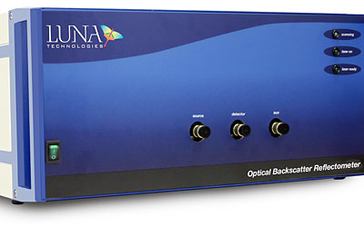
The 2004 Luna OBR Story
Luna Technologies introduced the Optical Backscatter Reflectometer as a highly sensitive frequency-domain reflectometer for fiber-optic component and assembly manufacturers. The original OBR gave designers and manufacturers a way to inspect optical components, modules, and assemblies with 125 dB sensitivity, 60 dB dynamic range, and 40 micron spatial resolution for up to 30 meters of optical length with zero dead zone.
Luna's optical backscatter reflectometer represented a new class of measurement instrument between conventional optical time-domain reflectometers and component-level reflectometers. OTDRs had long reach and backscatter-level sensitivity but relatively coarse resolution. Component reflectometers had high resolution but lacked backscatter-level sensitivity. With acquisition rates exceeding 5 million points per second, the OBR provided fast inspection, qualification, verification, and failure analysis for fiber-optic components and modules.
"We've created an ideal combination of speed, accuracy, sensitivity and resolution in an instrument that will be useful to anyone that assembles fiber-optic components," said John Goehrke, Chief Executive Officer at Luna Technologies. "Utilizing the OBR can dramatically improve component quality, significantly reduce testing costs, and ultimately improve production yield rate."
The original optical backscatter reflectometer came configured with an integrated internal tunable laser source, computer, and monitor.
What Changed Since 2004
Luna's current OBR 4600 shows how the category matured. Luna describes the OBR 4600 as an ultra-high-resolution optical backscatter reflectometer with 10 micron sampling resolution, zero dead zone, backscatter-level sensitivity, 80 dB dynamic range, and -130 dB sensitivity. Current documentation lists measurements including return loss, insertion loss, distributed loss, length, polarization states, phase derivative, and group delay.
The applications have expanded as photonics has moved closer to computing and sensing. OBR instruments are now used for silicon photonics research, photonic integrated circuits, fiber assemblies, short-run network diagnostics, aerospace and defense assemblies, medical fiber devices, distributed sensing, latency measurement, and high-volume manufacturing quality control.
OTDR Field Testing Still Matters
OBR instruments do not replace OTDRs for most field fiber work. A technician testing a metro, access, campus, FTTH, or long-haul span usually needs an OTDR with the correct wavelength, dynamic range, pulse width, launch cable, receive cable, event analysis, and reporting workflow. EXFO and VIAVI both emphasize launch and receive fibers because they let an OTDR measure the first and last connections around its dead zone.
Good OTDR practice still depends on basics: clean connectors, correct test wavelength, launch fiber matched to the link, bidirectional testing where required, proper pulse width, sufficient averaging, correct event thresholds, and careful interpretation of ghosts and reflective events. Automated tools can simplify trace analysis, but they do not eliminate the need to understand the measurement.
Choosing the Right Reflectometer
- Use an OTDR for installed fiber links, long distances, outside plant, construction acceptance, break location, and service restoration.
- Use an OBR/OFDR instrument for short optical assemblies, modules, photonic chips, component defects, microbends, latency, and high-resolution failure analysis.
- Check wavelength range. A 1310 nm link, 1550 nm link, PON, DWDM system, or silicon photonics device may need different source and detector behavior.
- Match range and resolution. Higher resolution often means shorter range or more specialized setup.
- Use launch and receive cables when OTDR dead zones would hide the first or last connector.
- Inspect and clean connectors before testing. Dirty interfaces can dominate the trace and damage equipment.
- Save baseline traces for critical links and components so later degradation can be compared against a known-good state.
Common Mistakes
- Using an OTDR as a replacement for insertion-loss certification without understanding what the acceptance standard requires.
- Testing a short patch cord with a long-range OTDR setup and then misreading events hidden by dead zone.
- Ignoring receive fibers and therefore missing or mismeasuring the far-end connector.
- Assuming a reflective event is always a bad splice; it may be a connector, mechanical interface, crack, open end, or ghost.
- Comparing traces taken at different wavelengths, pulse widths, launch fibers, or averaging settings as if they were identical tests.
- Forgetting that APC and UPC connectors have different reflection behavior and should not be mixed.
Reflectometry is one of the most useful diagnostic techniques in fiber optics because it gives location as well as loss. The practical art is choosing the right instrument for the scale of the problem: kilometers of outside plant, meters of jumper and module assembly, or millimeters of photonic device detail.
References
- Luna: OBR 4600 Optical Backscatter Reflectometer
- Luna: Optical Backscatter Reflectometry overview and applications
- Luna: OBR 4600 launch announcement
- EXFO: OTDR testing solutions and launch/receive cable context
- VIAVI: important factors when choosing an OTDR
- FOA: fiber optic reference, launch, and receive cables
- Fraunhofer IZM: Optical Backscatter Reflectometer laboratory description