Fiber optic connectors look simple from the outside, but they decide whether a fiber link is clean, low-loss, serviceable, and compatible with the equipment at each end. The connector is the mechanical interface that aligns the glass cores closely enough for light to pass from one fiber to another, or from a fiber into a transceiver, patch panel, splitter, or test instrument.
When this article was first published in 2006, field-installable pre-polished connectors were a major labor-saving improvement over epoxy-and-polish field work. That is still true, but the connector landscape has broadened. LC connectors dominate many enterprise and data-center transceivers. SC connectors remain common in broadband, passive optical networks, older patch fields, and equipment rooms. MPO and MTP-style multifiber connectors carry many fibers in one plug for dense trunks, parallel optics, and breakout systems. The right connector choice now depends on density, fiber type, polish, loss budget, cleaning discipline, and the exact optics being used.
Common Connector Types
- LC: A small-form-factor latch connector widely used on SFP, SFP+, SFP28, QSFP breakouts, and modern enterprise patch panels. Duplex LC is the default for many two-fiber links.
- SC: A square push-pull connector that is larger than LC and still common in telecom rooms, fiber-to-the-home installations, media converters, and some optical network terminals.
- ST: A bayonet-style connector often found in older multimode campus and building systems. It is less common for new high-density installations.
- FC: A threaded connector used where vibration resistance or precise connection stability matters, including some test, industrial, and legacy telecom environments.
- MPO/MTP: A multifiber push-on connector family used for high-density trunks and parallel optical links. MPO-style assemblies require special attention to fiber count, key orientation, pinning, polarity, and whether the end face is flat-polished or angled.
- Newer small-form connectors: CS, SN, MDC, and similar very-small-form-factor connectors are appearing in high-density data-center designs, especially where equipment vendors need more fiber ports in the same panel space.
Polish: UPC Versus APC
The letters after the connector type are just as important as the connector body. LC, SC, FC, and MPO describe the mechanical format. UPC and APC describe the polish geometry on the fiber end face.
- UPC: Ultra Physical Contact connectors have a straight polished end face and are commonly blue on single-mode assemblies. UPC is typical for many Ethernet transceivers and general data links.
- APC: Angled Physical Contact connectors use an angled end face, commonly 8 degrees, to reduce reflected light. APC is common in passive optical networks, RF video over fiber, some long-haul systems, and other reflection-sensitive links. APC connectors are commonly green.
- Do not mate APC to UPC: The bodies may appear to fit, but the end faces do not align correctly. Mixing APC and UPC can create high loss, high reflection, and physical end-face damage.
Color is a helpful clue, but it is not a substitute for reading the part number, transceiver requirement, patch-panel label, or provider documentation. The safest rule is to match connector body, fiber type, and polish at every mated interface.
Single-Mode, Multimode, and Loss Budget
Connector selection is tied to the fiber and the optical budget. Single-mode links usually use OS2 fiber and laser optics for long reach, access networks, and high-speed data links. Multimode links use OM3, OM4, or OM5 fiber for shorter links in buildings and data centers. A connector may physically fit while still being wrong for the fiber or optics.
Every mated pair adds insertion loss. Dirty, scratched, badly cleaved, or mismatched connectors add even more. That loss can be the difference between a link that passes and one that fails intermittently when temperature, movement, or equipment aging changes the margin. In dense patching areas, a good label and cleaning process can save far more time than the connector itself costs.
Cleaning and Inspection
Modern fiber practice is built around a simple rule: inspect, clean if needed, and inspect again before mating. IEC 61300-3-35:2022 covers visual inspection of fiber optic connector and transceiver stub end faces, including debris, scratches, defects, and contamination. Visual inspection does not replace measured performance testing such as insertion loss and return loss, but it helps prevent avoidable damage and troubleshooting.
- Keep dust caps on until the moment of connection, but do not assume a capped connector is clean.
- Use purpose-made fiber cleaning tools and lint-free materials rather than general shop wipes.
- Inspect both sides of a mated pair: the patch cord connector and the port, adapter, or transceiver.
- Never look into a fiber connector with the naked eye. Use proper inspection equipment and observe laser safety procedures.
- Replace damaged cords instead of polishing or reusing them in critical links.
Field Termination Choices
Installers now have several practical ways to put connectors on fiber. The best choice depends on volume, environment, skill level, tool budget, and whether the work is new construction, restoration, or a small add-on.
- Factory-terminated assemblies: These usually deliver the most predictable performance and are common for trunks, cassettes, harnesses, and planned data-center builds.
- Fusion-splice pigtails: A factory-polished connector is spliced to the installed fiber. This is common in telecom, outside plant, and high-quality single-mode work.
- Splice-on connectors: These combine fusion splicing with a connector body and can reduce tray space or avoid separate pigtail storage.
- Pre-polished mechanical connectors: These use a factory-polished stub and a mechanical splice inside the connector. They are fast and useful for field repairs, small jobs, and locations where full polishing is impractical.
- Epoxy-and-polish connectors: Still used in some production or specialty environments, but less common for routine field work because they require more tools, time, and craft consistency.
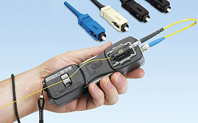
The 2006 Panduit OptiCam Story
Panduit SC OptiCam Pre-Polished Fiber Optic Connectors were introduced as a way to provide field termination in less than half the time of traditional field-polish connectors. Their appeal was straightforward: a factory pre-polished fiber stub end face eliminated hand polishing in the field, reducing labor, scrap, tool count, and installation variability.
OptiCam technology used a cam mechanism to secure the fiber and buffer in one action, helping installers produce repeatable terminations. A dedicated termination tool provided a visual indication after the cam step, making the process easier to verify than older field-polish methods. Panduit has continued the OptiCam family, including OptiCam 2 tools and connectors for LC, SC2, and ST2-style terminations.
That original product note still fits an important category: field-installable connectors are about speed, flexibility, and restoration. They are especially useful behind walls, at cross-connects, in smaller moves/adds/changes, and in sites where ordering a custom factory assembly is slower than terminating the installed cable. The tradeoff is that workmanship still matters. Fiber preparation, cleave quality, cleanliness, strain relief, and testing decide whether a fast connector is also a good connector.
MPO and High-Density Links
High-density fiber systems add another layer of connector planning. MPO and MTP-style connectors may contain 8, 12, 16, 24, or more fiber positions, but not every position is necessarily used. A transceiver may require a specific fiber count, a specific pinned or unpinned connector, a specific key orientation, and a specific polarity method. A trunk, cassette, and patch cord can all be individually correct yet still produce a reversed transmit/receive path if the polarity plan is wrong, especially in dense 10 Gigabit Ethernet switch and faster fabrics.
For high-speed optics, always match the transceiver vendor's connector requirements. Some 100G, 200G, 400G, and faster links use duplex LC; others use MPO-12, MPO-16, or other multifiber interfaces. The connector type alone is not enough; the fiber mode, lane count, polish, and breakout mapping all have to align.
Practical Buying Checklist
- Match the connector body: LC, SC, ST, FC, MPO, MTP, CS, SN, MDC, or the exact format required by the equipment.
- Match the polish: UPC to UPC, APC to APC. Never assume a physical fit means optical compatibility.
- Match the fiber: OS2 single-mode or the correct OM3, OM4, or OM5 multimode grade.
- Check simplex, duplex, or multifiber requirements before ordering patch cords.
- For MPO/MTP, verify fiber count, pinned or unpinned gender, key orientation, polarity method, and breakout wiring.
- Budget for cleaning and inspection tools, not just connectors and patch cords.
- Test completed links for insertion loss, and test return loss where the application requires it.
The connector is a small part of a fiber project, but it is where many failures begin. A strong fiber installation is not just low-loss cable; it is the correct connector, the correct polish, clean end faces, good labeling, and a termination method matched to the job.