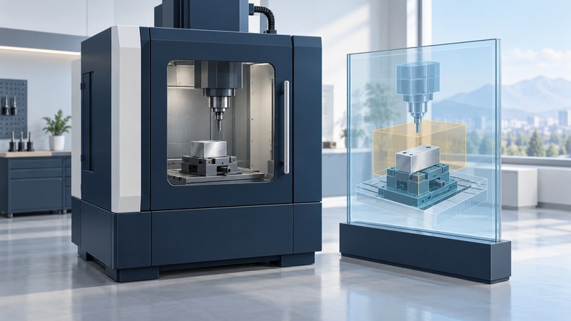
A CNC simulation becomes useful when its stock, tooling, fixtures, machine configuration and program match the job being reviewed. Real-time rendering helps a programmer see motion and material removal; a verification decision also needs explicit checks, tolerances and a record of what the model includes.
Choose the verification question
Start with a concrete question: will the tool holder clear a clamp, does a rotary move exceed travel, or does the finished stock leave excess material? Record the intended machine, control configuration, setup revision and responsible programmer. A rendered surface finish is a visual treatment; dimensional comparisons require their own calculation and tolerance settings.
MachineWorks' machine-simulation description connects stock models with collision detection and describes swept-volume checks within specified tolerances. Ask the software owner which moving pairs, stock interactions and motions the configured system actually checks.
Keep the digital setup aligned with the job
On narrow screens, scroll the table horizontally. Keyboard users can focus it and use the arrow keys.
| Input | Retain | Question to resolve |
|---|---|---|
| Workpiece | Initial stock, target model, units and coordinate systems | Does the stock include allowances and prior operations? |
| Tool assembly | Cutter, holder, extension and stick-out | Are nearby non-cutting surfaces represented? |
| Workholding | Clamps, jaws, fixtures and their positions | Does the geometry match the intended setup? |
| Machine and control | Axis relationships, limits and configuration | Which cycles, macros and control behaviors are supported? |
| Program | Exact file, revision and referenced subprograms | Is the run based on CAM path data or the posted NC program? |
Vericut's explanation of G-code verification distinguishes checking post-processed code from checking cutter-location data. Preserve that distinction in the review record. If the shop edits the NC file, offsets, tool assembly or fixture afterward, identify which checks must be repeated.
Review results as evidence
Run the planned checks through approach, cutting, retracts, tool changes and transitions between setups. Record excluded components and disabled checks. Save each event with its program location, relevant objects, configuration and a reproducible view. Then classify the event: confirmed interference, model error, intended engagement or unresolved condition.
Check the numerical comparison against the intended part, including both remaining stock and removed material. Choose a comparison tolerance appropriate to the question and model resolution. Display smoothness, zoom and animation speed are separate from the computational settings; document those settings instead of judging coverage by how fluid the animation looks.
Use a missing clamp to test the review process
Resolve the finding through the responsible manufacturing engineer's approved process. Update the model or program as appropriate, rerun affected checks and retain the review decision. A virtual result supports the shop's controlled setup and prove-out process; it does not establish actual fixture position or machine condition.
Deliver a review someone else can reproduce
Package the exact program, setup files, tool list, machine configuration, software version, comparison settings and event report. Give open questions an owner. Before release, compare the job's intended offsets and tool data with the reviewed configuration. Vericut's machine-connectivity documentation illustrates why work-offset correspondence is a distinct check; available connections and supported controls depend on the implementation.
For shared-model handling, use the CAD visualization guide. For a physical machine acceptance project, the vertical machining center guide connects simulation assumptions with representative parts and inspection evidence.
Use the working record
Download the editable working record. It includes the task-specific fields, instructions, fictional example and source references needed to preserve the evidence behind a decision. Complete it with the people responsible for the actual process.