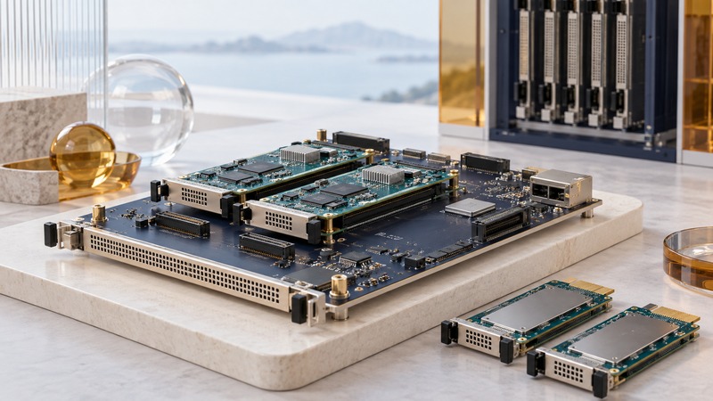
A carrier blade hosts smaller modules and connects them to a larger chassis. In the legacy IBM BladeCenter context, the SBS BCT4-AMC1 is a specific example: it brought AdvancedMC modules into a BladeCenter telecommunications system, with compatibility determined across the chassis, carrier, modules, firmware, and software.
Use this guide to document an existing configuration or evaluate the evidence for a proposed replacement. It provides an architecture and compatibility framework, not a procedure for installing or hot-swapping live equipment.
What the BCT4-AMC1 announcement establishes
The February 13, 2006 SBS announcement, preserved by Abaco, describes four AdvancedMC bays interconnected through PCI Express and Gigabit Ethernet switches. Bays 2 and 3 had x8 PCIe interfaces; bays 0 and 1 had x4. The BladeCenter T midplane connection used Gigabit Ethernet.
The announcement distinguishes two front-access bays from two internal bays. It describes hot-swap capability for the front modules and the carrier, IPMI 1.5 management, and telecom clock support. It also identifies an ASLP10 processor module in bay 2 as an example of providing the PCIe root complex.
Those are useful architectural facts about the announced carrier. They leave the exact module combination, software versions, service sequence, and supported replacement procedure to configuration-specific documentation.
Read AdvancedMC as a set of requirements
PICMG's AMC.1 specification overview explains how the PCI Express extension builds on AMC.0's mechanical, connector, management, power, and thermal requirements. The linked overview describes Revision 2 from 2008, so it is background to the standard family, not proof that a 2006 carrier implements that later revision.
A module's physical dimensions establish only one part of compatibility. A usable combination also needs the right signal connections, compatible host and endpoint roles, sufficient power and cooling, management support, and working software. Record the specific revision at each layer instead of filling a compatibility sheet with the word “standard.”
Build a compatibility record from the outside inward
Scroll the table horizontally. Keyboard users can focus it and use the arrow keys.
| Layer | Identify | Evidence to obtain |
|---|---|---|
| Chassis | Exact machine type, management module, power, cooling, and firmware | Supported-carrier list and applicable configuration instructions |
| Carrier | Part number, board revision, firmware, and bay map | Hardware manual and documented limits for that revision |
| Each module | Part number, revision, size, interface, and assigned bay | Compatibility statement covering the carrier and the intended function |
| Data and clock paths | PCIe roles and lanes, Ethernet routes, and required clocks | A documented path from the module to the application |
| Management and software | Management firmware, operating system, drivers, and application | A supported version combination and a known working configuration |
| Service | Replacement method, backups, and recovery responsibility | The exact maintenance procedure and a successful planned recovery test |
For each row, record the document title, revision, page or section, date checked, and result: supported, conflicting, or unknown. Keep a photograph of labels and an exported configuration with the record. Unknown is a useful finding because it identifies what must be resolved before a change.
Use a documented demonstration at its actual scope
The May 2006 SBS newsletter describes a planned BladeCenter T demonstration involving the BCT4-AMC1, ASLP10, Telum 1001-O3, and Telum 624 modules, with SUSE V9 Linux on the ASLP10. It is evidence of a named demonstration configuration and contemporary integration work. Preserve the distinction between that planned demonstration and a validated production installation.
Preserve the dependencies that make a legacy system useful
Keep firmware packages, permitted software copies, licenses, manuals, configuration exports, and recovery instructions together in a controlled archive. Record where each file came from and which hardware it belongs to. An unlabelled firmware file becomes a future ambiguity, especially when several revisions look alike.
Assess a legacy installation by the service it provides and the support evidence still available. A stock of spare boards helps only when those boards can be identified, integrated, and recovered within the organization's maintenance process.
Download the carrier compatibility record (plain text). For chassis-wide power and failure planning, see Dense Blade Servers; for data-transfer measurements, see High-Speed Cluster Interconnects.