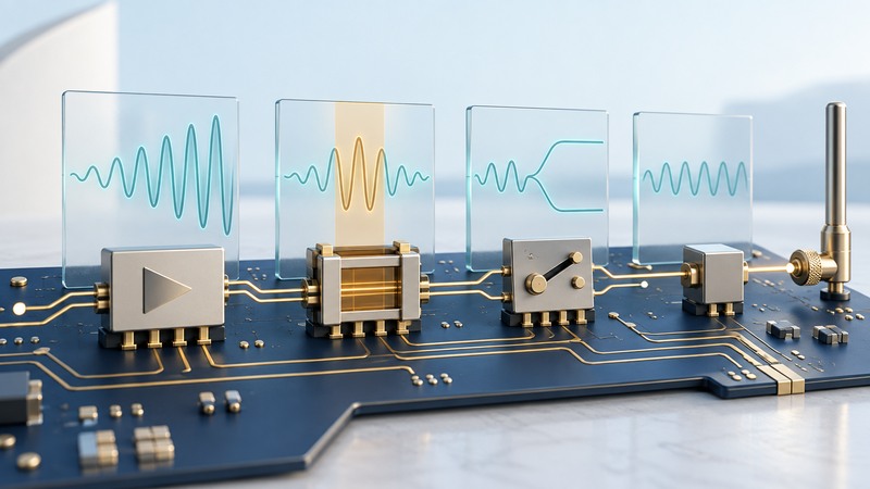
A wireless RF front end sits between the radio circuitry and the antenna. Its amplifiers, filters and switches condition signals as they leave or enter the device. Read its specifications as a chain of gains, losses, noise and operating limits tied to a particular frequency and waveform.
This explanation is for readers interpreting a module block diagram or comparing component data sheets. It provides a way to ask the right questions; an actual RF design also requires the manufacturer's reference circuit, layout guidance and suitable measurement equipment.
Follow transmit and receive paths
On transmit, a power amplifier increases the radio signal's power while trying to preserve the modulation accurately enough for the intended link. A filter restricts unwanted frequency content. A switch may route the antenna between transmit and receive paths or between bands. The exact order and integration vary by architecture.
On receive, a filter can reduce unwanted signals reaching the receiver, and a low-noise amplifier increases a weak desired signal while adding as little noise as practicable. Filtering before the LNA can protect it from strong unwanted signals, but insertion loss ahead of the amplifier also affects the receive noise budget. Analog Devices' receiver front-end reference design illustrates the tradeoff between a low-noise input path and preselection for stronger unwanted signals. Read the actual reference design for the intended architecture.
Scroll the table horizontally; keyboard users can focus it and use the arrow keys.
| Block | Useful function | Specifications to read together |
|---|---|---|
| Power amplifier (PA) | Raises transmit output power. | Output power, modulation quality, gain, efficiency, supply and temperature. |
| Low-noise amplifier (LNA) | Amplifies weak received signals. | Noise figure, gain, linearity, input limits and current. |
| Filter | Passes the intended band and attenuates unwanted frequencies. | Passband loss, rejection, bandwidth, power handling and temperature behavior. |
| RF switch | Selects an RF path. | Insertion loss, isolation, power handling, control levels and switching timing. |
A front-end module can integrate several of these blocks. Integration reduces some external connections while preserving the need to check the complete chain, control sequence, antenna interface and thermal design.
Distinguish power, gain and usable output
dBm expresses absolute power relative to 1 milliwatt. dB expresses a ratio, so gains and losses can be added along a defined path. A component's strongest possible output and its usable output for a particular modulation can be different operating points.
Fictional transmit budget: a PA delivers 23 dBm at its output pin and the following switch, filter and interconnect lose 2 dB in total. The conducted power reaching the antenna feed is 21 dBm. Using P(mW) = 10P(dBm)/10, those levels are about 199.5 mW and 125.9 mW. The path therefore delivers about 63.1% of the PA's output power to that reference point. Antenna gain, mismatch and radiation behavior require separate treatment.
This arithmetic describes a specified path at a specified frequency. It does not supply a coverage radius. A link's received signal also depends on the antenna arrangement, propagation, bandwidth, receiver performance and interference.
Read modulation and thermal conditions
A transmitter must preserve the waveform well enough for the chosen modulation. Error vector magnitude (EVM) describes modulation error; read an output-power claim alongside its EVM requirement, signal bandwidth and test configuration. Stronger drive can raise distortion and heat, changing the usable operating point.
Qorvo's 2019 Wi-Fi front-end thermal-design article discusses PA efficiency and linearity, LNA noise figure, switch loss and filter behavior as temperature changes. Its practical lesson is to evaluate the assembled operating condition, including the board and heat path, rather than treating a room-temperature headline as the whole specification.
For receive sensitivity, noise figure is one part of the budget. A high-gain LNA can also be challenged by a strong nearby transmitter. Check linearity and blocking conditions as well as the small-signal noise specification, especially when multiple radios share a compact product.
Compare data sheets at matching conditions
- Mark the exact frequency band, channel bandwidth and modulation used by the application.
- Record the reference planes: chip pin, module connector or antenna feed.
- Compare typical, minimum and maximum values separately, including supply voltage and temperature.
- Confirm whether a stated power meets the relevant waveform-quality condition and whether other paths are active.
- Include external losses, required matching components, control states and layout constraints.
- Identify the measurements needed on the assembled board: conducted output and quality, receive behavior, thermal limits and coexistence under representative traffic.
When one candidate advertises higher output and another better efficiency, first align their test conditions. If the conditions differ, obtain comparable evidence or mark the comparison unresolved. For network symptoms after equipment is installed, use a wireless site survey to connect radio observations with real client tasks.