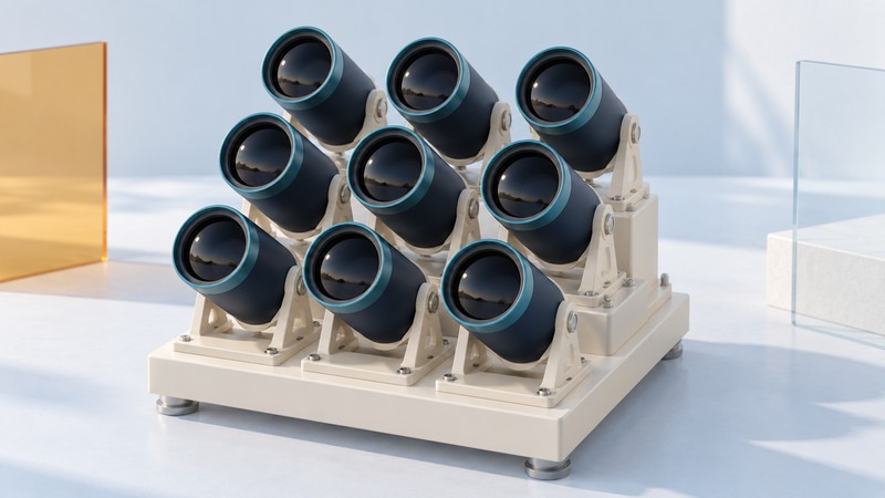
A distributed-aperture telescope uses multiple collecting apertures as parts of one observing system. To understand its capabilities, ask two questions: how much light do the apertures collect, and how are their optical signals or recorded images combined?
The phrase covers different architectures. Some preserve the wave relationships needed for interference; others align and combine images recorded by separate cameras. This difference determines what an “effective aperture” claim tells you.
Separate collecting area from angular resolution
Collecting area describes the area admitting light. Angular resolution describes the ability to distinguish nearby details on the sky. For an interferometer, the separation between apertures—the baseline—and the observing wavelength set the scale of the fine detail it can probe. Larger separations at the same wavelength reach finer angular scales.
There are still gaps between the apertures. An array can therefore have the angular resolving capability associated with a much wider instrument while collecting far less light than a filled aperture of that width. Baseline orientations and lengths also determine which spatial information is sampled. ESO's interferometry explanation shows why both array geometry and light collection matter.
Read “equivalent diameter” together with the quantity it describes. An area-equivalent diameter answers a light-collection question. A baseline-based comparison answers a resolution question under the stated observing conditions.
Three ways to combine apertures
| Approach | What is combined | What to look for in a claim |
|---|---|---|
| Phased optical imaging array | Light from multiple modules with controlled relative optical paths | Phasing performance, usable field, image quality, and collecting area |
| Long-baseline interferometer | Signals from separated telescopes used to measure interference | Wavelength, baselines, sampling, calibration, and reconstruction method |
| Image-combining array | Independently recorded images aligned and combined in processing | Single-channel image quality, detector sampling, exposure, and control of background errors |
The first two approaches share coherent-combination principles; they are useful descriptive categories, not rigid boundaries. Star-9 provides a historical phased-imaging example below, while ESO's VLTI illustrates long-baseline operation.
Dragonfly: another meaning of distributed aperture
In their 2022 paper on the Dragonfly Telephoto Array, Abraham and colleagues describe co-aligned lenses with separate cameras, aimed at low-surface-brightness imaging. Image stacking and control of scattered light serve that observing goal. The paper also discusses data processing and mechanical flexure as practical challenges.
Moving such cameras farther apart does not, by itself, turn their image stack into a coherent interferometric observation. Look to the individual optics, atmosphere, sampling, and processing for the delivered image resolution. The paper is a dated account of that design; its planned expansion schedule should be read in its 2022 context.
Why optical path control matters
Coherent combination depends on the relative phase of arriving light waves. Differences in optical path shift those relationships. A working system must compensate for geometric path differences and keep changing disturbances within its operating tolerances.
ESO's VLTI delay-line description identifies internal path differences, changing source geometry as Earth rotates, and faster effects from atmospheric turbulence and mechanical vibration. Moving optical components adjust the path before beam combination.
This explains why pointing several telescopes at the same object is only a starting point. A coherent system also needs a path-control and measurement strategy. For a proposed instrument, ask what was measured, over what wavelength band and field, and for how long useful combination was maintained.
Worked example: nine apertures and two layouts
Consider nine identical, unobscured circular apertures, each 0.10 m in diameter. This is a hypothetical geometry exercise, not a specification for Star-9. Assume the same transmission and ignore optical losses.
One aperture has area π × (0.10 ÷ 2)² ≈ 0.00785 m².
Nine have total area 9 × π × 0.05² ≈ 0.0707 m².
The filled-circle diameter with that area is √9 × 0.10 = 0.30 m.
Moving the same nine apertures farther apart keeps that total geometric area unchanged. The larger separations change the available baselines for coherent combination. The delivered image still depends on the system and its measurements.
The 0.30 m figure expresses equal geometric collecting area only. Transmission, detector response, background, and exposure enter a sensitivity comparison. For a resolution comparison, establish the wavelength, combination method, and sampled baselines separately.
Star-9: a phased-imaging prototype reported in 2006
On June 27, 2006, Lockheed Martin reported its Star-9 prototype (PDF), a nine-aperture imaging telescope. The announcement described tests of module phasing and imagery over a useful field. It also proposed configuring groups of modules for different wavelengths, polarizations, or viewing tasks.
The historical value is the engineering question it addressed: how to coordinate smaller optical modules to obtain useful imaging performance. The release is a manufacturer's account of prototype work. It supplies no basis here for a claim that Star-9 is a currently deployed observatory or that every sparse array delivers the same cost, reliability, or field-of-view benefits.
Read an array-performance claim with six questions
- What is being observed? Record the target, wavelength, field, and required detail. A result for a bright point-like object may answer a different question from an extended faint scene.
- What is the collecting area? Record aperture count and diameters, with losses or obscurations where known.
- How are the inputs combined? Identify coherent beams, correlated signals, or stacked images.
- What does “equivalent” mean? Require the claim to name resolution, collecting area, sensitivity, or another specific quantity.
- What was demonstrated? Separate measured images and calibration results from simulations and proposed capabilities.
- What makes the result repeatable? Look for alignment, stability, processing, maintenance, and operating-condition evidence.
For example, a claim that an array is “equivalent to a one-meter telescope” is incomplete until the author specifies the relevant performance measure. Ask for that definition before applying the comparison to another observing task.
For personal viewing equipment, the binocular selection guide explains magnification, exit pupil, field of view, and handling. Return to the Telescopes and Binoculars guides for both starting points.