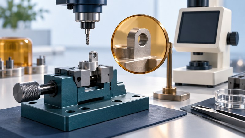
Micro machining succeeds when the feature can be made, handled, and measured with the required consistency. Start with the smallest functional features and their acceptance requirements, then evaluate the process and inspection method together.
This guide helps designers and precision shops prepare a supplier brief. Have a controlled drawing, material and condition, expected quantity, critical surfaces, and the feature's function. State dimensions and tolerances in explicit units; a general request for high precision leaves too much unresolved.
Describe what the feature must do
For each critical feature, identify size, depth, aspect ratio, corner radius, surface requirement, datum relationship, and permitted edge condition. Explain whether it guides fluid, locates a pin, seals, transmits motion, or merely provides clearance. That function helps the designer and machinist negotiate a practical geometry without losing the purpose.
Include access for tools, flushing, deburring, cleaning, and measurement. A dimension on a drawing becomes harder to verify when the relevant surface is buried inside a narrow passage. Ask the supplier to mark features that require a different process, an inspection section, or an agreed surrogate test.
On a narrow screen, scroll the table horizontally. Keyboard users can focus it and use the arrow keys.
| Process | Useful discussion | Evidence to request |
|---|---|---|
| Micro milling | Cutting-tool access, radius, runout, material condition, burr formation and deflection. | Representative feature, tool strategy, edge condition, and inspection results. |
| Wire EDM | Conductive workpiece, through-cut geometry, wire access/start hole and surface requirements. | Cut geometry, entry/exit condition, finishing approach and measured taper. |
| Sinking or drilling EDM | Conductive material, electrode access, wear, flushing, and required cavity or hole form. | Electrode/process plan and evidence for depth, size and surface integrity. |
Makino's micro-machining discussion connects small-feature work with thermal stability, tooling, runout, and EDM approaches. Its machine examples are demonstrations with particular setups. Treat advertised capability as a reason to request a representative trial rather than as a guarantee for a different part.
Control the complete setup
Tool runout and deflection can be significant relative to a small feature. Discuss the actual tool and holder assembly, projection, spindle condition, fixture support, and method for detecting wear or breakage. The supplier should establish cutting or discharge settings for the material and equipment; scaling down a familiar large-part recipe is an uncertain starting point.
Record how the part is loaded and released. A fragile wall can move under clamping force and relax afterward, so agree on the state in which it will be inspected. Include cleaning and deburring in the route and verify the feature afterward. A burr removed by an uncontrolled operation can change the edge that performs the function.
Temperature belongs in both machining and inspection records. Allow the workpiece and measurement setup to reach the condition required by the agreed method. Keep the material, fixture, and environmental assumptions with the result so another shop can interpret the same drawing consistently.
Choose measurement before cutting the trial
Define the measured feature precisely: for example, a slot width at a named depth and location, in a specified part condition. Agree on datum establishment, optical edge selection or probe access, sampling, calibration evidence, and uncertainty. NIST's guidance on method-defined measurements explains that uncertainty includes how the method is implemented, beyond simple repeatability.
NIST's dimensional calibration guide discusses agreeing how uncertainty is used with tolerance decisions. Use the applicable current contractual standard for the actual inspection; the fictional interval above is an explanation, not a universal acceptance rule.
Approve repeatable evidence
Order a trial that includes the difficult features, material condition, fixture, and complete finishing route. Request individual measurements and records across enough representative parts to assess the intended production decision. One excellent sample demonstrates possibility; repeated work across the expected conditions is needed to assess consistency.
Retain rejected examples and identify the mechanism behind them: geometry, tool condition, fixture behavior, finishing damage, or measurement disagreement. Set a reaction plan for drift before releasing production. Revisit the brief after changes in material, tooling, fixture, machine, or inspection software. The machining-center evaluation guide covers the wider machine and part-family comparison.
Use the working record
Download the editable micro machining feasibility record. Save a copy, complete the actual requirements and evidence fields, and review open issues with the responsible owner. The plain-text record includes instructions, units where needed, the fictional example, and source references.