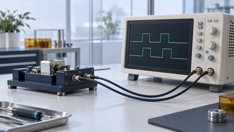
A timing result becomes comparable when the measured events and acquisition conditions are explicit. Define the edges, voltage thresholds, reference and statistic before choosing an instrument setting. For production test, preserve those definitions with the raw observations and software version.
Define the start and stop events
A time interval is the elapsed time between two specified events. A clock period can be measured between successive rising edges; a propagation delay can be measured between an input transition and the corresponding output transition. Include polarity and threshold in either definition.
NIST's time-interval explanation describes a counter starting and stopping as its inputs reach their trigger levels. Consequently, a comparison needs the same event definition, including which crossing is selected when a waveform rings or contains more than one transition.
Record probes, cables, termination and channel assignment. Measure or compensate channel-to-channel delay according to the instrument procedure, retaining the calibration evidence. Keep the physical setup stable while comparing devices or software revisions.
Choose the statistic that answers the question
On a narrow screen, scroll the table horizontally. Keyboard users can focus it and use the arrow keys.
| Quantity | What is compared | Context to retain |
|---|---|---|
| Period variation | Individual cycle durations | Edge definition, event count and reported spread |
| Cycle-to-cycle difference | One period minus its preceding period | Sign convention and whether absolute maximum or another statistic is used |
| Time interval error (TIE) | Observed edge time against a reference edge time | Reference or clock-recovery definition and filtering |
| Propagation delay | Associated input and output events | Thresholds, load, channels and event pairing |
Tektronix's jitter application note explains the role of timing measurements and their time trends in investigating a signal. Save the metric configuration with the result. RMS, standard deviation, peak-to-peak spread and a largest adjacent difference require their own names and definitions.
Work through a small period record
Fictional dataset: five periods are 9.98, 10.01, 10.00, 10.02 and 9.99 ns. Their mean is 10.00 ns. The largest minus smallest is 10.02 − 9.98 = 0.04 ns, or 40 ps.
Subtracting each preceding period gives +30, −10, +20 and −30 ps. The largest absolute adjacent difference is 30 ps. It answers a different question from the 40 ps peak-to-peak period spread.
Five samples illustrate the arithmetic. A production conclusion needs a justified observation length, representative operating conditions and the applicable decision rule. Retain missing or invalid observations explicitly rather than treating them as zero.
Check the measurement system before judging the device
Read the instrument's timing accuracy conditions, timebase specification and calibration requirements. Include threshold noise, signal slope, probe/loading effects, channel skew and reference uncertainty where relevant. A fine displayed time increment describes resolution; determine the uncertainty applicable to the actual measurement separately.
Repeat a stable control signal and, where practical, repeat the setup independently. Inspect the waveform and time trend when a distribution changes. A threshold or acquisition change may alter the result even when the device behavior is unchanged.
Agree on bandwidth, sample rate, record duration, number of acquisitions, exclusions and statistical treatment before comparing systems. Preserve those settings in the measurement logging record. For electrical device behavior under applied bias, the companion parametric testing guide addresses a different measurement plan.
Use the working record
Download the editable timing measurement record. Save a copy, complete the actual requirements and evidence fields, and review open issues with the responsible owner. The plain-text record includes instructions, units where needed, the fictional example, and source references.