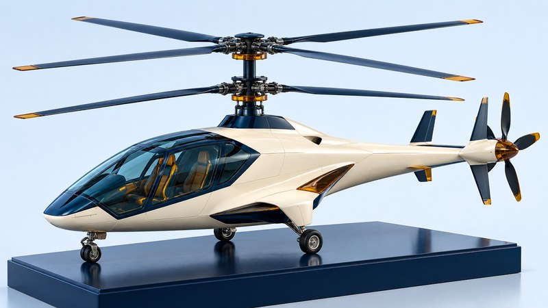
A coaxial helicopter places two main rotors on the same axis, turning in opposite directions. Sikorsky’s X2 demonstrator combined that arrangement with a rear pusher propeller and other technologies to explore higher forward speeds. Understanding the combination makes its flight-test results more informative than a headline speed alone.
Recognize the two propulsion roles
The main rotors provide lift and control. Counter-rotation lets the two rotor systems oppose each other’s torque, while the pusher propeller adds forward thrust. Sikorsky’s X2 program account identifies the coaxial rotors, auxiliary propulsion, fly-by-wire controls, drag reduction and active vibration control as parts of an integrated system.
“Coaxial” describes where the rotors sit. “Compound” describes a helicopter design that adds devices such as auxiliary propulsion or wings. An aircraft can combine both ideas, but the word coaxial alone does not establish the presence of a pusher propeller.
Why forward speed becomes difficult
As a helicopter moves forward, the advancing and retreating sides of a rotor encounter different relative airflow. At increasing speed, retreating-blade behavior and high airspeed on the advancing side contribute to important design limits. The FAA Helicopter Flying Handbook provides the underlying explanation of rotor aerodynamics.
In a counter-rotating arrangement, the advancing sides occur on opposite sides of the aircraft. X2 couples its rotor concept with a propeller dedicated to added forward thrust. This offers designers a different way to allocate lift and propulsion, while bringing its own requirements for transmission, controls, rotor clearance and vibration management. It is a system tradeoff to evaluate through testing.
Read the X2 result as a test milestone
Sikorsky reported that the demonstrator reached 253 knots in level flight on September 15, 2010. Its July 2011 retirement announcement recorded approximately 22 total flight hours across 23 test flights. Those figures document a research program’s achievement under its test conditions.
A test result answers what the demonstrator achieved. A transport mission also needs payload, endurance, environmental conditions and operating limits. Use dated documentation for the particular follow-on aircraft before assigning it any demonstrator capability.
Compare missions with the same questions
On small screens, focus this table and use the arrow keys to scroll.
| Claim | Evidence to seek | Practical meaning |
|---|---|---|
| Top speed | Level flight or descent, airspeed definition and test conditions | Establish exactly what was demonstrated. |
| Range | Payload, fuel, reserves and flight profile | See whether the figure matches the proposed mission. |
| Hover capability | Weight, altitude, temperature and relevant limits | Understand the conditions behind vertical-lift performance. |
| Service readiness | Specific aircraft status, approvals and operating documentation | Distinguish development progress from an available service. |
For a fictional medical-transport comparison, a cruise-speed advantage matters only within a complete mission: reaching the aircraft, loading, flying, landing and transferring the patient. That is a planning framework, not a claim about any operator or aircraft.
Use the explanation at the right level
This guide helps readers interpret rotorcraft designs and reporting. Flight instruction, performance planning and emergency procedures require the specific aircraft’s approved documentation and qualified training. For a broader understanding of simulated training, see the flight simulator guide.