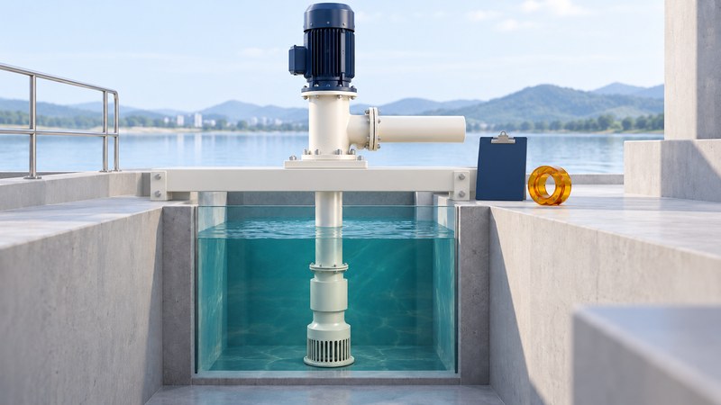
A vertical turbine pump moves liquid through a submerged bowl assembly and up a vertical column. In a common lineshaft arrangement, the motor sits above the liquid and drives the impellers through a long shaft. For a water facility planning a replacement, the useful starting point is the required hydraulic duty and the existing installation—not a familiar model name alone.
Follow the liquid and the power
The Wilo explanation of vertical turbine pumps describes the major assemblies. Liquid enters at the lower suction bell, passes through the impeller and diffuser stages, travels up the column and leaves through the discharge head. The motor supplies rotation through the shaft; bearings support that rotating assembly.
On a narrow screen, scroll the table sideways. Keyboard users can focus the table region and use the arrow keys.
| Assembly | Role | Information to locate |
|---|---|---|
| Bowl and impellers | Add energy to the liquid in one or more stages. | Bowl model, stages, impeller details and performance curve. |
| Column and lineshaft | Carry liquid upward and transmit rotation to the bowls. | Setting length, shaft construction, bearings and lubrication arrangement. |
| Discharge head | Connect the vertical assembly to delivery piping and its support arrangement. | Outlet orientation, flange, mounting and dimensional drawing. |
| Driver and thrust arrangement | Supply power and accommodate the specified mechanical loads. | Motor ratings, speed, coupling and thrust requirements. |
A vertical appearance alone does not establish interchangeability. Wet-pit and double-casing designs, shaft arrangements and liquids differ. The Flowserve VTP/VPC user instructions, document 71569224 EN illustrate why the order-specific drawings and equipment documentation belong with the general manual.
Define flow and head together
Flow is the volume delivered per unit time, such as liters per second or gallons per minute. Head expresses energy per unit weight of liquid as an equivalent height, commonly meters or feet. The required duty combines the desired flow with the head needed to overcome elevation, pressure differences and losses in the system. The DOE pump-selection guidance also calls for liquid properties and the expected range of operation.
A pump curve describes performance at a stated speed and configuration. A system curve describes what the installation requires at different flows. Their intersection determines an operating point. Review the expected operating range, efficiency, power and suction requirements with the supplier; a nameplate power rating alone leaves those questions unanswered.
DOE’s guidance on matching pumps to system requirements recommends measuring actual conditions and investigating mismatches such as heavy throttling or bypass flow. Replacing a unit offers a chance to confirm today’s duty instead of perpetuating an old oversizing assumption.
Prepare a replacement brief before requesting a quote
Start with the installed pump’s serial number, nameplate photographs, purchase records, certified curve and general-arrangement drawing. Then add measured operating data with units, timestamps and operating conditions. Mark missing information explicitly; a blank field is easy to mistake for an irrelevant requirement.
On a narrow screen, scroll the table sideways. Keyboard users can focus the table region and use the arrow keys.
| Topic | What to supply | What the reviewer should resolve |
|---|---|---|
| Hydraulic duty | Normal and limiting flows, required head, measured performance and control method. | Expected operating range and compatibility with the system. |
| Liquid and inlet | Composition, temperature, solids, water-level range and intake geometry. | Materials, submergence, cavitation margin and inlet conditions. |
| Physical fit | Setting length, mounting, outlet dimensions, access and drawings. | Clearances, structural support, pipe loads and removal method. |
| Electrical and mechanical | Supply, driver ratings, speed, shaft and thrust details. | Compatibility and the complete approved arrangement. |
| Continuity | Required service, available standby equipment, spares and outage constraints. | Procurement plan, installation responsibilities and acceptance criteria. |
Download the pump replacement brief (editable plain text). Fill it from records and approved measurements, attach the drawings, and have the responsible engineer or supplier resolve each open item. Keep the reviewed version with the quote so alternatives can be compared against the same duty.
Keep condition records that explain changes
The DOE pump-maintenance guide separates routine preventive work from condition monitoring. Trends in vibration, operating measurements and efficiency can reveal deterioration before a complete failure. Compare readings taken under similar operating conditions; a change in tank level or valve position can explain a change in load.
A useful record identifies the pump, date, speed, flow, pressure or head, water level and the measurement method. Add observed vibration, leakage or alarms and the person who reviewed them. Use the manufacturer’s limits and facility procedures to decide the response. A generic symptom list cannot diagnose a bearing, hydraulic or electrical fault reliably.
Plan the return to service as part of the replacement
Storm resilience requires a usable service plan as well as a spare pump. Record who can authorize an outage, identify the approved standby arrangement and specify the documents needed before a replacement is accepted. Ask the supplier to state what is included, what is excluded, and which dimensions or duties remain unconfirmed.
The Flowserve instructions require the specified operating conditions and address equipment-specific startup checks. Qualified personnel must apply the correct lifting, energy-isolation, alignment, lubrication and commissioning procedures. Changed service conditions require manufacturer review. Keep submerged-pump checks, electrical work and access to wet wells within the facility’s approved professional procedures.
Before closing the job, retain the final drawings, curve, settings, commissioning results and maintenance schedule. That record gives the next team a verified starting point when a storm or equipment failure compresses the time available for decisions.