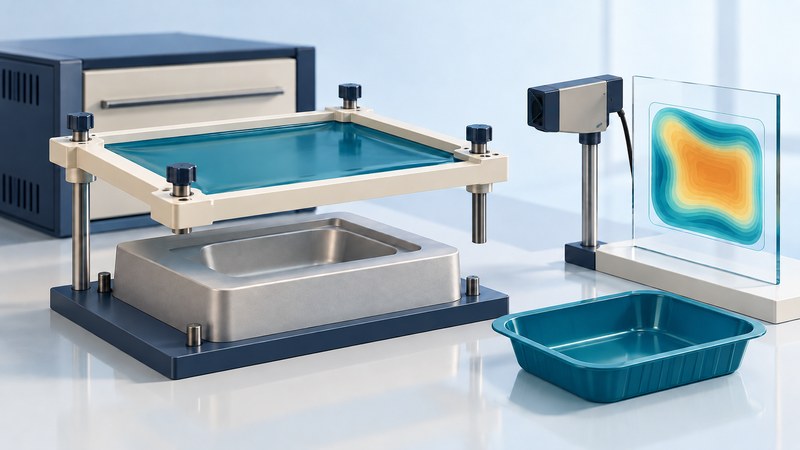
A thermoforming temperature map is useful when its locations can be related to the sheet, the heating system, and the finished part. Pair the map with material and process records, then test whether a planned change improves the required part characteristics.
This guide helps thermoforming engineers investigate an established process. Start with the exact sheet grade, gauge and lot, tooling identity, approved operating window, imager documentation, and a defined defect or thickness requirement. Machine changes belong to trained staff following the equipment and site procedures.
Separate heater settings from sheet condition
A heater setpoint describes the controlled equipment variable. The sheet's condition also depends on its material, thickness, color, residence time, heating arrangement, and starting temperature. Measure at a repeatable process point and retain the time between heating, measurement, and forming.
Fluke Process Instruments' thermoforming overview emphasizes temperature distribution and sufficient heat penetration across the sheet. A surface reading alone leaves the through-thickness condition unresolved, particularly for thicker material. Establish the measurement's relevance with the sheet supplier and process engineer.
Infrared instruments require appropriate spectral response and settings for the actual plastic and geometry. Record emissivity assumptions, reflections, any window or obstruction, and whether the material can transmit radiation in the instrument's band. Use a supplier-supported measurement method. The industrial infrared thermometer guide explains target size, optics, reflections, and comparison measurements.
Register each image to the physical sheet
Define a sheet origin, travel direction, clamped edges, and the locations sampled. Preserve those references after forming so the same areas can be found on the part. Mark the associated heater zones in the record without assuming a one-to-one relationship: stretching redistributes material.
Motion changes the mapping from a scan to a location. Fluke's thermoforming system description includes correction for rotary-machine images. Check how your own system uses position or speed information, handles acceleration, and identifies each sheet. Validate registration with an approved reference procedure; an attractive thermal picture can still be spatially misaligned.
On a narrow screen, scroll the table horizontally. Keyboard users can focus it and use the arrow keys.
| Symptom | Check together | Measure after the trial |
|---|---|---|
| Webbing | Heating pattern, mold layout, material flow and forming sequence. | Location and frequency of folds on identified parts. |
| Incomplete detail | Sheet condition, vacuum/pressure performance, vents and timing. | Defined feature geometry and repeatability. |
| Local thinning | Original gauge, stretch path, heating distribution and plug/tool interaction. | Thickness at fixed locations after the specified conditioning. |
| Distortion after release | Cooling, mold condition, release timing and handling. | Dimensions at a defined time and temperature after forming. |
Plaskolite's VIVAK fabrication guide lists multiple causes for symptoms such as webbing and incomplete detail. Its numerical processing guidance applies to that material and document. Use the relevant sheet-grade instructions for your work; the symptom table above is a way to organize evidence, not a universal adjustment recipe.
Run a trial with a fixed comparison
Choose one problem, mark the measurement locations, and record baseline parts with their temperature maps. Define the planned change, the conditions held constant, and what result would justify adopting it. Preserve vacuum/pressure timing, tooling temperature, sheet orientation, cooling, and measurement timing as relevant to the process.
Keep individual readings and reject observations. A higher average at one location can coexist with thinning elsewhere or worse dimensional fit. Compare the complete acceptance set and repeat the preferred condition across representative lots and production circumstances.
Preserve the relationship, then monitor it
Release the approved recipe with sheet specification, tooling revision, image-registration settings, measurement method, acceptable part results, and reaction plan. Keep a small set of representative maps linked to identified parts so later investigations can recover the context.
Recheck the relationship after changes to gauge, resin grade, color, recycled content specification, tool, heater, motion, or imager. If the temperature pattern returns to baseline but defects remain, broaden the investigation to the other forming and measurement variables rather than forcing a temperature explanation.
Use the working record
Download the editable thermoforming trial record. Save a copy, complete the actual requirements and evidence fields, and review open issues with the responsible owner. The plain-text record includes instructions, units where needed, the fictional example, and source references.