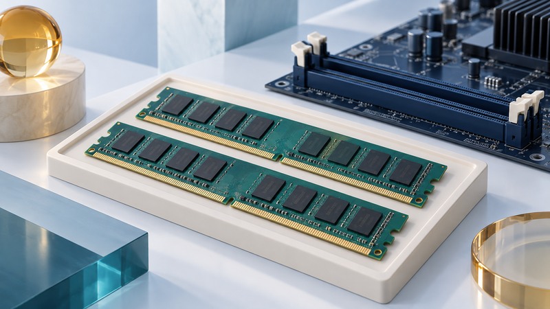
DDR2 SDRAM remains relevant when maintaining an older computer or embedded system. A successful replacement matches the whole memory module to the platform: generation, form factor, electrical design, organization and capacity. Start with the computer’s exact model and service manual, then decode the module label.
Separate the chip from the module
SDRAM means synchronous dynamic random-access memory; DDR2 is one generation within that family. A component listing describes an individual memory chip, while a DIMM listing describes a board populated with chips. The capacities use different units: Gb means gigabits; GB means gigabytes.
For a concrete component example, Micron’s DDR2 catalog lists MT47H64M16NF-25E AAT:M as a 1 Gb, x16 component with 400 MHz clock, 800 MT/s data rate and 1.8 V supply. Those are chip specifications, not a promise that a particular computer accepts a module built from that chip.
Photograph the complete module label, including suffixes. Use the module manufacturer’s data sheet to identify capacity, rank count, chip organization, ECC and buffering. Counting visible chips is an unreliable substitute for the part number.
Read a real DDR2 module specification
Kingston’s KVR800D2N6/2G data sheet, dated October 20, 2011, describes a 2 GB DDR2-800 CL6, 240-pin, 1.8 V module. Its illustrated configuration is 2Rx8 with sixteen 128M × 8-bit components. The document also notes that component combinations and module height can vary under the part number.
On narrow screens, focus the table and use the arrow keys or swipe to see every column.
| Specification | Meaning for the replacement | Evidence to collect |
|---|---|---|
| DDR2 and form factor | Generation and connector layout must fit the platform. | Exact module type in the service manual; compare the keying without forcing insertion. |
| Capacity and organization | Equal total GB can hide different chip densities or rank arrangements. | Supported module capacities and organization, plus the candidate data sheet. |
| ECC and buffering | Error-correction and buffer designs are platform choices. | Required ECC/non-ECC and unbuffered/registered/fully buffered type. |
| Voltage and timings | The controller must support the module’s operating conditions. | Specified supply, supported speed and timing profiles. |
| Population order | Slots and channel pairs may have a required installation pattern. | Numbered-slot diagram and pairing instructions for this motherboard. |
Here, 2R identifies two ranks, and x8 describes each chip’s data width in the specified organization. A rank is a group of chips accessed together across the module’s data bus. For systems requiring FB-DIMMs, use the separate fully buffered DIMM guide; the presence of DDR2 chips alone does not identify an interchangeable desktop module.
Understand DDR2-800 and PC2-6400
Worked bandwidth example: double data rate transfers data on both clock edges. A 400 MHz I/O clock therefore gives 800 million transfers per second, written 800 MT/s. Across a 64-bit data path, each transfer carries 8 bytes: 800 million × 8 = 6,400 million bytes/s, or 6.4 GB/s. That theoretical rate explains the PC2-6400 designation.
This is a bus calculation. Application throughput also depends on access patterns, timing delays and the processor/controller. A faster-rated module only runs at a setting supported by the complete system. Record the actual operating setting after installation rather than treating the label as a measured result.
Use platform exceptions as a purchase gate
The Dell OptiPlex 745c user guide specifies non-ECC DDR2 and explicitly excludes 2 GB 800 MHz modules in its memory specification. That is enough to reject a candidate matching that excluded combination, even when its generation and pin count fit. This example is scoped to the 745c documentation; other OptiPlex variants need their own specifications.
When a manual contains conflicting capacity statements or differs from a seller’s listing, resolve the disagreement with model-specific support documentation before ordering. Save the reference and revision beside the part number. A used module advertised as “high density” needs an actual organization specification, not an assumption that every DDR2 controller can address it.
Check the replacement in stages
- Record the installed capacity, slot population and symptoms before changing anything. Back up work and follow the system’s shutdown, power-disconnection and electrostatic-handling instructions.
- Install only the supported combination in the documented slots. Keep the original modules identified so you can restore the baseline.
- Check the firmware’s recognized capacity and reported speed. A successful boot is the first observation, not the entire acceptance test.
- Run the manufacturer’s memory diagnostics, then repeat the workload that motivated the change. Record errors, freezes or capacity discrepancies.
- If results differ, return to the supported baseline and change one factor at a time. Investigate module support, seating and slot population before changing voltages.
Operating-system address limits can reduce usable memory even when firmware recognizes the installed total. The broader memory-upgrade guide helps distinguish capacity needs from other performance bottlenecks.