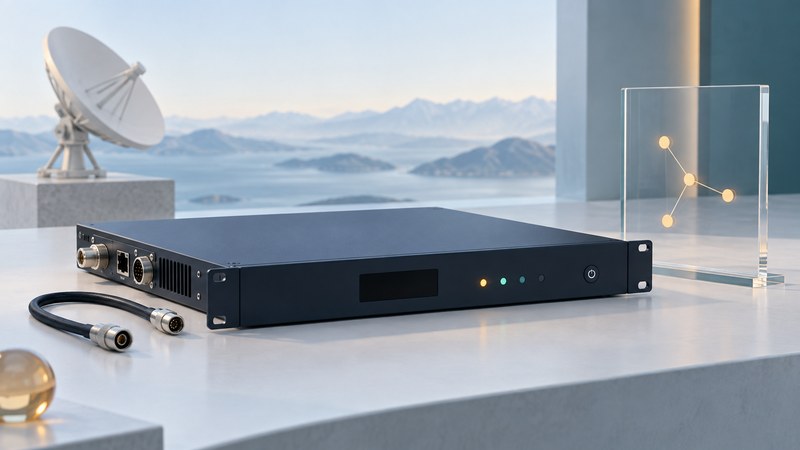
A satellite modem converts traffic into a waveform that the satellite network can carry and recovers received traffic at the other end. Selecting one starts with the network's approved waveform and interfaces. Troubleshooting starts with recorded status and a known configuration, because an impressive maximum data rate cannot establish compatibility or explain every outage.
Confirm compatibility before comparing maximum rates
Identify whether the service supplies a managed terminal or permits an independently selected modem. In a managed service, the provider's terminal and software may be integral to authentication, scheduling and network access. Replacement requires explicit provider compatibility and provisioning.
For an engineered link, obtain the approved configuration from the network operator: transmit and receive frequencies, symbol rates, modulation, forward error correction, framing, polarization, interfaces and permitted transmit power. Match the outdoor converter, amplifier, reference clock and DC-power arrangement as well as the modem.
DVB's DVB-S2 specification page describes framing, coding and modulation for broadband satellite applications. A standard name alone is incomplete: supported options, enabled features, firmware and the chosen operating mode must agree at both endpoints.
Keep three kinds of rate separate
Scroll the table horizontally on small screens. Keyboard users can focus the table region and use the arrow keys.
| Number | Meaning | Interpretation |
|---|---|---|
| Symbol rate, symbols/s | How quickly modulation symbols are transmitted. | Combines with modulation and filtering to determine bandwidth needs. |
| Coded and information bit rates, bit/s | Bits represented by symbols and the share available after error-correction coding. | Higher-order modulation or a higher code rate changes link requirements. |
| Useful application throughput, bit/s | Data that the user application actually receives. | Framing, network headers, scheduling, retries and traffic conditions reduce usable capacity. |
| Eb/N0 or Es/N0, dB | Energy per bit or symbol relative to noise spectral density. | Compare the correct metric with the requirement for the configured mode. |
Interpret link quality with the configured mode
A demodulator needs adequate signal quality for its modulation and coding. A mode carrying more useful bits can need a different operating margin. Automatic coding or modulation changes may therefore alter throughput as conditions change. Record the active mode with each measurement.
Use the manufacturer's definition of receive level, Eb/N0, Es/N0, error counters and alarm thresholds. A high composite receive power can include unwanted signals. The NASA communications overview explains the broader link-budget relationship among transmit power, antenna performance, path loss and received signal quality.
Compare a failing interval with a known working baseline from the same configuration. Confirm carrier identity, demodulator lock and useful packet delivery separately from the receive-level reading.
Collect evidence in layers
- Preserve the baseline. Export or record the current configuration, model, firmware, enabled options and event times before changes.
- Check local traffic. Record interface link status, error counters, addressing and whether the application can reach the local gateway.
- Read the modem state. Capture carrier lock, active mode, receive-quality metrics, error counts and exact alarms.
- Compare receive settings. Check the documented frequency plan, symbol rate and coding against the operator's approved configuration.
- Correlate both ends. Ask the network operator to compare gateway logs, outages, weather and capacity conditions at the same time.
Keep inspection and logging separate from transmit changes. Coordinate frequency, power, waveform and antenna adjustments with the operator and follow the equipment procedure. Unplanned changes can disrupt the intended link and other users sharing capacity.
Use symptoms to narrow the next check
No carrier lock: compare the receive configuration and recorded alarms with the approved setup; ask whether the expected carrier is present. Lock with rising errors: compare signal quality, active mode and weather with the baseline. Clean receive counters but poor application performance: inspect local networking, congestion, traffic policy and the far-end application.
After an approved change, repeat the same representative traffic test and retain the before-and-after logs. If the evidence does not isolate the cause, restore the documented baseline when instructed and escalate with the collected record. Avoid guessing a universal acceptable Eb/N0 threshold; it depends on the mode and implementation.
Make the support handoff reproducible
Use the modem diagnostic record for synchronized observations at both ends. Keep credentials out of the log and share configuration files through the operator's approved channel.
For the wider connection path, see satellite communications. For verifying a delivered enterprise service, use the acceptance and failover guide.
Sources and further reading
Source links reviewed September 28, 2026. Check current service terms, equipment documents and operational notices when applying the guide.