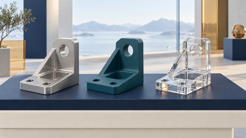
A useful CAM view makes a particular feature easy to inspect. Metallic shading helps communicate shape, while flat shading, edges, transparency and sections can reveal details hidden by reflections or other solids. Keep the model and viewpoint fixed when comparing modes, then use the appropriate numerical check for a machining decision.
Name the feature before choosing the view
Record the model revision, stock or simulation state and the review question. Examples include whether a pocket is visible, which solid hides a feature, or whether apparent faceting comes from the display representation. Save the camera, projection, clipping planes and visible objects so another reviewer can reproduce the view.
The geometry representation matters as well as the surface appearance. MachineWorks 8.8 release notes distinguish analytic-surface ray tracing, mesh simplification and playback transparency. Those are version-specific capabilities; the CAM application's integration determines which controls reach its users.
Use display modes as diagnostic views
On narrow screens, scroll the table horizontally. Keyboard users can focus it and use the arrow keys.
| Mode | Helpful for | Watch for |
|---|---|---|
| Metallic or reflective | Communicating curvature and the overall machined form | A bright reflection can conceal a shallow feature or suggest an apparent edge. |
| Flat or matte shading | Reducing reflection distractions; revealing face or mesh transitions | Facets may belong to the representation; inspect the underlying geometry. |
| Edges or wireframe | Tracing boundaries and narrow features | Overlapping rear edges can make depth ambiguous. |
| Transparency | Seeing a component behind a fixture or another solid | Transparency settings and overlap can complicate depth interpretation. |
| Section or clipping plane | Exposing a cavity or an internal relationship | Record plane position and orientation; a clipped view omits material outside it. |
Use the modes available in the actual application. Compare the same orientation first, then rotate deliberately to resolve depth. For a section, save a second view showing where the cutting plane lies.
Turn an ambiguous image into a check
If the feature remains unclear, check visible-body filters, clipping, tessellation or sampling settings and the simulation state. Change one display setting at a time and preserve before-and-after views. If the underlying geometry changes between captures, label that comparison as a different model state.
Keep the visual finding tied to numerical evidence
A screenshot can document where a reviewer looked. For clearance, gouge or stock comparison, preserve the relevant calculated result, units, tolerance and involved solids as well. MachineWorks 8.8, for example, documents hard-clash thresholds that affect whether an intersection is reported; a clean-looking display supplies no substitute for those settings.
Finish with a short finding: feature, view state, observation, confirming check and disposition. Use CNC simulation and verification for the machining checks and controlled material and finish rendering when the decision concerns appearance.
Use the working record
Download the editable working record. It includes the task-specific fields, instructions, fictional example and source references needed to preserve the evidence behind a decision. Complete it with the people responsible for the actual process.