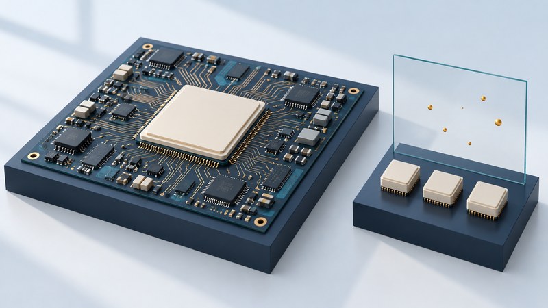
An FPGA can provide flexible digital processing in a satellite, but radiation tolerance is a set of characterized behaviors under stated conditions. Read the device, test method, environment and mitigation assumptions together. A marketing label or a history of flight use is the beginning of an assessment, not the complete evidence for a new mission.
Separate cumulative damage from individual events
Scroll the table horizontally on small screens. Keyboard users can focus the table region and use the arrow keys.
| Term | What it describes | Question for the test report |
|---|---|---|
| Total ionizing dose (TID) | Accumulated ionizing exposure that can change device behavior or parameters. | What dose, material reference, bias, dose rate, temperature and pass criteria were used? |
| Single-event upset (SEU) | A radiation-induced change in stored state, such as a memory bit. | Which resources were tested, with which particles, conditions and error-detection coverage? |
| Single-event functional interrupt (SEFI) | A disruption requiring a defined recovery action. | What stops working, how is it detected and what reset or reconfiguration restores service? |
| Single-event latch-up (SEL) | A potentially destructive high-current condition in susceptible structures. | What was tested, what immunity or limit is claimed, and what protection is required? |
AMD's space-device characterization page reports TID and single-event information separately and identifies device-specific data. Preserve that specificity: a dose figure and a particle-effect threshold express different quantities. Neither one alone describes the complete behavior of an implemented FPGA system.
Some detailed vendor reports require controlled access. Record an inaccessible report as an open evidence item and request it from the vendor. Use the exact part, grade, revision and applicable manufacturing information for the assessment.
Put the mission beside the component
Record orbit or trajectory, duration, shielding assumptions, duty cycle, operating temperature and acceptable consequences of faults. Connect the environmental analysis to the device tests and to the functions that the FPGA implements. A recovered telemetry gap may be acceptable in one experiment and unacceptable in another task.
The ECSS radiation-mitigation handbook brings together techniques across the IC and electronic-system development flow. ECSS identifies it as guidance rather than requirements. Determine the applicable project requirements separately and use the handbook to support an explicit engineering argument.
Keep “tested,” “modeled,” “specified” and “assumed” as separate labels in the evidence record. Flight heritage is useful when the environment, design, configuration and observed performance are relevant; state the differences that still need analysis.
Connect each mitigation to a failure mode
Redundant logic and voting can allow a design to tolerate selected faults, but the voters, clock, reset, routing and shared resources also need analysis. Error detection and correction can protect memory within the code's capabilities. Configuration scrubbing checks or repairs configuration state. Watchdogs and recovery controllers can detect a stall and trigger a defined response.
AMD's configuration SEU documentation describes configuration-memory detection and correction for the specified architecture. Assess application-state restoration and functional-interruption recovery separately from configuration-memory repair.
Choose mitigations for the actual failure modes and validate their implementation. Consider faults in the mitigation machinery itself, common-mode failures, detection latency and the behavior of outputs during recovery. A reset that restores computation may still interrupt the mission's useful service.
Check the units before using a rate
Distinguish cross-section units from orbit-predicted rates, and bit-level figures from device-level events. If a report quotes an immunity threshold, retain its particle, test conditions and coverage. An extrapolation needs its own stated model and uncertainty.
Ask for a verification chain
- Characterize the exact device. Collect the current datasheet, radiation reports, errata and applicable qualification evidence.
- Map critical functions. Identify memories, configuration, processors, interfaces, clocking and shared resources used by the implementation.
- Define fault responses. State what must be detected, tolerated, corrected, reset or escalated, including the maximum acceptable interruption.
- Test implementation behavior. Use appropriate analysis, fault injection and radiation testing under the project's verification plan.
- Measure recovery. Record time to detect, time to restore valid outputs, data lost and any manual intervention.
- Control the configuration. Retain bitstream, tools, settings, constraints and mitigation versions associated with the evidence.
A fault-injection test covers the injected fault model and observed behavior. Define its coverage alongside physical characterization to identify the mechanisms and behaviors still requiring evidence.
Create an evidence record with explicit gaps
Use the FPGA radiation-evidence checklist to connect each claim to a report, condition and design consequence. Leave missing reports and untested recovery paths visible for the responsible engineer.
Reassess when the part, orbit, mission duration, bitstream, tool flow or mitigation implementation changes. This guide supports reading and organizing evidence; flight acceptance requires the project's engineering and assurance process. For the system budgets around the device, continue with small-satellite mission tradeoffs.
Sources and further reading
Source links reviewed September 28, 2026. Check current service terms, equipment documents and operational notices when applying the guide.