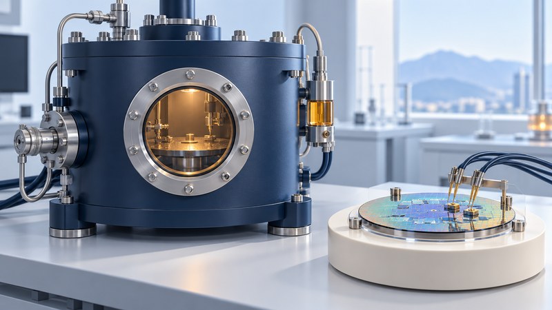
Pressure-chamber probing connects a controlled mechanical stimulus with electrical measurements on sensor dies. A useful test brief defines the pressure reference, device condition, temperature and measurement sequence, then states how offset, sensitivity, hysteresis and repeatability will be evaluated.
Start with the device and pressure reference
Identify the die, wafer map, sensor architecture, electrical connections and intended measurement range. State whether pressure is absolute, gauge or differential, and identify what reaches each relevant side of the sensing structure. The chamber's pressure reading and the pressure difference across a diaphragm can represent different quantities.
WIKA's explanation of pressure references distinguishes an absolute reference from a reference to ambient atmosphere. Record the reference convention with every pressure value and specify units explicitly. A number followed only by “bar” leaves part of the test definition unresolved.
Define the complete test environment
FormFactor's vacuum and pressure system overview describes wafer probing in controlled environments for MEMS and other measurements. Actual pressure, temperature, medium and probe-access capabilities depend on the specified system and configuration.
Have the qualified equipment owner confirm chamber ratings, approved media, connections, interlocks and operating procedures. This article is a test-planning guide, not instructions for operating or modifying a pressure vessel. Keep device operating characterization separate from proof-pressure or destructive testing, each of which needs its own approved method and limits.
On narrow screens, scroll the table horizontally. Keyboard users can focus it and use the arrow keys.
| Variable | Record | Why it matters |
|---|---|---|
| Pressure | Reference, units, reference instrument and achieved values | Defines the physical input rather than the requested setpoint. |
| Temperature | Chuck/device evidence, stabilization rule and timestamps | Connects the reading with thermal condition. |
| Electrical setup | Supply, bias, sense path, range and compliance | Defines the stimulus and measured output. |
| Sequence | Ascending/descending points, dwell and repeats | Allows directional and time-dependent effects to be compared. |
| Identity | Wafer, die coordinates, contact status and raw-data file | Keeps each result attached to the correct device. |
State how each result is calculated
For a chosen interval, sensitivity can be expressed as output change divided by pressure change, with units such as mV/bar. Define offset at a stated reference pressure. Report nonlinearity against an explicitly chosen reference line and express its denominator, such as full-scale output span.
The WIKA pressure-measurement handbook describes hysteresis as the output difference at the same pressure on rising and falling sequences. Compare matched points after the specified stabilization rule. Repeating one direction addresses repeatability; changing temperature addresses a different dependence. Preserve all three distinctions in the data.
Work through a directional difference
If the difference changes between runs, review achieved pressure, stabilization, reference uncertainty, contact quality and thermal history before assigning it to the sensor. Use controls or repeated measurements designed to isolate the suspected contribution.
Retain results at the tested level
Report sample count, wafer locations, excluded data and the reason for each exclusion. Keep raw output and pressure records alongside extracted parameters. A wafer-level result describes the tested die and environment; packaging can change stress, access and thermal behavior, so later package-level qualification remains a separately defined step.
Use the parametric-testing guide for the electrical measurement path and the MEMS packaging guide for cavity, bonding and package-function questions. Approve the test brief with both the device owner and equipment owner before collecting release evidence.
Use the working record
Download the editable working record. It includes the task-specific fields, instructions, fictional example and source references needed to preserve the evidence behind a decision. Complete it with the people responsible for the actual process.