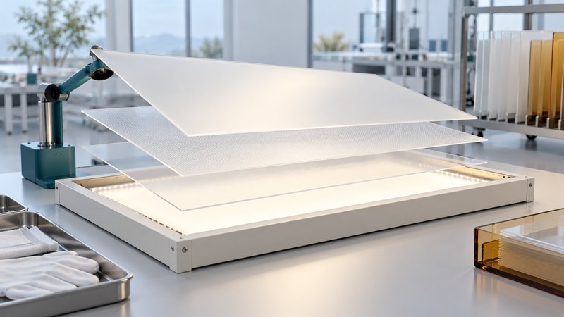
Evaluate an optical diffuser film at two levels: the measured properties of the film and the performance of the assembled backlight. Begin with the display's brightness, uniformity, viewing and environmental requirements. Use supplier data to identify candidates, then compare them in a controlled stack.
Keep the optical quantities separate
Total transmission describes how much light passes under the stated measurement conditions. Haze describes a specified portion of transmitted light scattered away from the incident direction. An angular distribution describes where the outgoing light goes. Each helps answer a different design question.
BYK's transparency-measurement white paper explains transmission and haze measurement geometry. Preserve the method, sample thickness, spectrum and instrument conditions when comparing numbers. A haze value by itself leaves the angular distribution and assembled display performance unresolved.
For a directional diffuser, request the angular definition and incident-light conditions. Luminit's diffuser FAQ describes full width at half maximum (FWHM) angles and an orientation-dependent tradeoff between transmission and source hiding for its microstructured products. Verify the behavior of the particular film rather than treating every diffuser as interchangeable.
Build a controlled backlight comparison
Record the source, drive setting, warm-up condition, reflector, light guide and every film in stack order. Mark the sample orientation using a method that does not contaminate the optical area. Keep spacing, clamping and measurement geometry fixed while changing the candidate film.
On a narrow screen, scroll the table horizontally. Keyboard users can focus it and use the arrow keys.
| Question | Measure or observe | Keep constant |
|---|---|---|
| Are bright spots concealed? | Luminance grid and visible source structure | Source pitch, stack spacing and drive |
| Is useful brightness maintained? | Luminance at defined viewing angles | Instrument geometry and operating temperature |
| Does the film remain flat? | Wrinkles, bow, movement and optical artifacts | Mounting and environmental exposure |
| Can it survive assembly? | Scratches, contamination and handling yield | Handling procedure and inspection lighting |
Use the supplier's handling and mounting instructions for the exact construction. A cleaning process acceptable for one film may alter another surface. Preserve an unexposed control when evaluating temperature, humidity or light exposure.
State the uniformity formula beside the result
Fictional fixed-grid trial: candidate A has a minimum luminance of 420 cd/m² and a maximum of 500 cd/m². Using minimum divided by maximum, its uniformity is 84%.
Candidate B gives 450 and 490 cd/m², so the same ratio is 91.8%. B has a better ratio in this trial and a lower measured maximum. Keep the full grid and average luminance, then compare every acceptance requirement before choosing.
This explicitly defined ratio is a trial metric. Another specification may use a different grid or formula, which changes the meaning of its percentage.
Repeat the comparison after reassembly to reveal mounting sensitivity. Inspect the intended viewing angles and operating states. A single centered photograph is useful for documenting visible artifacts, while quantitative acceptance requires the agreed measurements.
Approve the construction and its operating conditions
Review substrate, coatings, adhesives and mechanical retention together. Obtain the permissible operating conditions for the full construction. A heat-deflection test result is one material measurement; establish service suitability through applicable supplier limits and the planned assembly qualification.
Record before-and-after optical data and dimensions for the specified exposures. Keep scratches, yellowing, delamination and warpage as distinct observations. If a result changes, determine whether the film, mounting or another stack component changed before assigning a cause.
Use the CAD visualization guide to communicate stack clearances and orientation, then retain the physical trial evidence with the released material specification.
Use the working record
Download the editable optical diffuser comparison. Save a copy, complete the actual requirements and evidence fields, and review open issues with the responsible owner. The plain-text record includes instructions, units where needed, the fictional example, and source references.