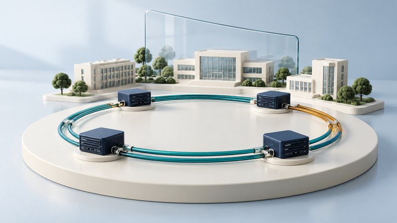
FDDI used a pair of counter-rotating rings to make a fiber LAN more resilient. Its most useful lesson is still practical: draw what happens after a specific failure, then check whether the alternate path is truly available.
How the ring earns its resilience
Fiber Distributed Data Interface is a 100 Mbit/s token-passing LAN technology associated with ANSI X3T9.5 and the ISO 9314 standards family. A station transmits when the access rules permit it to use the token. Dual attachment provides access to primary and secondary rings running in opposite directions. Cisco's FDDI troubleshooting reference describes the topology and fault-recovery behavior.
The primary ring normally carries traffic in the simple arrangement considered here; the secondary ring provides a recovery path. Real installations can include concentrators, single-attached stations, bypass arrangements, and other details. Establish which topology you have before interpreting a failure.
Trace one cable cut
Assume the cable span between B and C loses both ring connections, while all four stations and the remaining spans stay operational. B and C can wrap the ring, joining primary and secondary paths into one surviving loop.
This example establishes recovery from one defined span failure. Multiple failures can partition a ring, and a shared loss of power or equipment can defeat paths that look redundant on a diagram. Cisco's FDDI port-adapter overview (PDF) illustrates dual and single attachment and the consequences of a second failure.
Apply the lesson without copying the old topology
FDDI belongs mainly to networking history and legacy support. Switched Ethernet and routed designs address backbone capacity and resilience through different mechanisms. The useful inheritance is a method for testing claims about alternate paths.
| Claim | Question to resolve | Useful evidence |
|---|---|---|
| “There are two cables.” | Do both follow the same conduit, entrance, or patch panel? | A physical route drawing and an identified shared-risk inventory. |
| “There are two switches.” | Do they share power, control, or an upstream bottleneck? | Power and dependency diagrams, plus the actual failure scenario. |
| “Failover is fast.” | Which failure, detection method, and traffic recovery measurement are meant? | A planned test recording disruption and application recovery separately. |
| “Both links are active.” | How is traffic distributed, and what capacity remains after one fails? | Forwarding behavior and representative load measurements. |
For modern link aggregation, consult IEEE 802.1AX; for a specified Ethernet ring-protection architecture, consult ITU-T G.8032. A protocol choice must fit the equipment, topology, recovery requirement, and operations team. Ring-shaped cabling alone does not determine the appropriate forwarding design.
Inspect an inherited FDDI installation
- Identify adapters, concentrators, attachment types, fiber media, connectors, and management access.
- Draw primary and secondary paths and mark their shared physical risks.
- Record station/ring state, errors, bypass arrangements, and the applications relying on the network.
- Determine whether endpoints can move to Ethernet or require supported gateways or application replacement.
- Plan migration acceptance around service behavior, connectivity, and recovery, with a rollback route.
Use the actual hardware manual for optical limits and cable handling. Schedule any failure testing with the system owner; an inherited control or laboratory network can have dependencies missing from the network drawing.
The design question FDDI makes visible is durable: after the particular failure you care about, trace the complete surviving path and prove that the service can still use it.