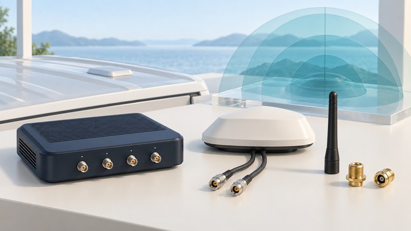
Choose a mobile antenna as part of a complete radio system: supported frequencies, antenna ports, cable runs, and installation all matter. This guide concerns external antennas for mobile routers and vehicle communications equipment. Begin with the exact router and modem manuals, then build a compatibility record before buying hardware.
Map cellular, Wi-Fi, and location antennas separately
A vehicle router may use cellular radio for its internet connection, Wi-Fi for local devices, and GNSS for location. One roof enclosure can contain several antenna elements with separate cables. Label the function of each lead and the matching router port; the outside shape alone tells you little about the connections inside.
The Ericsson Cradlepoint antenna reference distinguishes transmitting/receiving cellular and Wi-Fi paths from receiving GNSS paths, and emphasizes frequency matching and placement. Its guidance also explains that nearby objects and closely arranged antennas can affect performance. Use the corresponding guidance for your equipment.
Check how many antenna paths the modem requires and which combinations support its bands and MIMO operation. MIMO uses multiple radio paths; a multi-lead assembly needs its intended port mapping. Connecting just the lead that fits most conveniently can leave part of the system unused. Ordinary smartphones generally present a different, internally integrated antenna arrangement; use an external connector only where the manufacturer documents one.
Make a compatibility record
Scroll sideways for all columns. Keyboard users can focus the table and use the arrow keys.
| Item | Record from the documentation | Reason |
|---|---|---|
| Radio and frequencies | Router/modem variant, required operating bands, and antenna response over those bands. | A broad “5G” or “Wi-Fi” label is too coarse for a compatibility decision. |
| Ports and leads | Every port's function, MIMO pairing, connector family and contact type. | Similar-looking connectors and leads can serve different radio functions. |
| GNSS supply | Active/passive antenna requirement and any supported supply ratings. | An active receiving antenna needs the specified electrical support. |
| Cable assembly | Type, length, loss at each relevant frequency, adapters, and strain relief. | The radio receives the performance of the whole path. |
| Installation | Ground-plane requirements, mounting surface, spacing, environmental rating, and allowed gain. | The antenna must suit both the radio approval and the vehicle. |
Cradlepoint’s cables-and-ports guidance provides concrete examples of SMA versus RP-SMA, GNSS power requirements, and cable losses. Those assignments belong to the documented hardware. Confirm the connector body and center contact against both manuals; an adapter cannot supply missing frequency coverage or correct a wrong radio path.
Use the antenna-system worksheet to keep part numbers and the port map together. Ask the supplier to resolve an ambiguous specification before purchase.
Count cable losses alongside antenna gain
Antenna gain describes directional performance relative to a reference; dBi uses an ideal isotropic radiator as that reference. Read the gain pattern and frequency-specific data rather than treating the largest advertised number as a universal improvement. A passive antenna's shape redistributes radiation; it is a different component from an active signal booster.
Check whether a quoted gain includes the supplied cable. For example, POYNTING’s PANL-431 specifications explicitly identify gain excluding cable loss. For a simple comparison at one frequency and direction, subtract cable and connector loss from antenna gain. Avoid subtracting the same cable loss again if it is already included.
Plan mounting around the actual vehicle and manuals
Check whether the antenna needs a conductive ground plane, what orientation it specifies, and how other roof equipment affects the proposed location. Plan cable routing, bend radius, weather sealing, and strain relief as part of the installation. Have a qualified installer handle vehicle penetrations and uncertain mounting or electrical details.
The IBR900/IBR1700 vehicle-installation guidance directs installers to the antenna instructions and router-specific separation requirements. It also shows why lead pairing is model-specific. Use the requirements for your own router, antenna, region, and installation; there is no single spacing or tightening instruction suitable for every assembly.
Compare the same conditions before and after
Before making a permitted change, record the equipment, firmware, carrier, location, vehicle orientation, connected band when available, and router-reported signal metrics. Repeat the same modest data or calling task. Follow the manufacturer's shutdown and handling instructions when changing antenna connections.
Afterward, return to the same stationary location and orientation and repeat the observations at several relevant times. Record signal quality as well as strength, and note if the modem selected a different cell or band. A faster download during one trial can also reflect network load or a different connection; it does not isolate the antenna's contribution.
Use the results to make a specific support request: the original configuration, the exact change, the port map, and repeated observations. For the service side of the problem, see coverage and compatibility checks and mobile-data troubleshooting.