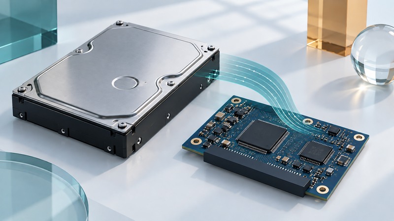
A SATA hard drive contains a computer dedicated to storing and retrieving data. Its controller connects host commands with signal processing, buffers, error handling and mechanical positioning. Following those functions explains why the speed printed beside “SATA” is only one part of drive performance.
Distinguish the host controller from the drive controller
The host-side SATA controller connects the computer to the storage device. Inside the hard drive, a separate controller interprets commands and coordinates the machinery needed to fulfill them. A system-on-a-chip combines several of these electronic functions in one integrated circuit; the exact partition varies by drive generation and design.
Seagate’s Mozaic 3+ architecture description gives a later-generation example: its integrated controller consolidates read-channel processing, disk management and data-exchange protocols, with a servo core for positioning. Those functions explain the architectural role. Its process technology and implementation details belong to that product generation.
Follow a read request through the drive
A useful historical reference is the Momentus/M8 product manual, chapter 5. Its functional descriptions connect the host interface, buffer, read channel, servo system and firmware. In a simplified read, the drive receives a logical-block request, checks available cached data, positions the head if media access is needed, interprets the head’s signal, applies error checking/correction and returns data or an error status.
On narrow screens, focus the table and use the arrow keys or swipe to see every column.
| Function | Role in the simplified data path |
|---|---|
| Host interface | Which command and logical blocks did the computer request? |
| Buffer management | Where can incoming or outgoing data wait? |
| Read channel | What data can be recovered from the sampled head signal? |
| Error correction | Do the decoded data satisfy the code’s checks, or require correction/retry? |
| Servo control | How should the head follow the required track? |
| Firmware | How should commands, caching, faults and operating states be coordinated? |
A buffer can temporarily decouple the host connection from mechanical access. The historical manual’s write-cache description shows command completion occurring before data reaches the disk in a supported cached-write sequence. Persistence therefore depends on the applicable command, cache policy and power-loss behavior. Evaluate those from the exact drive and storage-system documentation.
Calculate the interface ceiling separately
SATA rates are expressed in gigabits per second. SATA-IO’s interface FAQ describes 8b/10b encoding, which sends ten line bits for eight data bits. Framing and other protocol work also consume capacity.
Worked ceiling: for a 6 Gb/s link, 6 × 8/10 = 4.8 Gb/s after the encoding adjustment. Dividing by eight bits per byte gives 0.6 GB/s, or 600 MB/s in decimal units, before further protocol overhead. This is an interface calculation, not a measured platter-transfer rate.
For a hypothetical drive delivering 180 MB/s during a long sequential read, transferring 90 GB would take at least 90,000 ÷ 180 = 500 seconds, or 8 minutes 20 seconds, assuming the source keeps that rate and the destination keeps up. Using the link’s 600 MB/s ceiling would predict 150 seconds and understate the time. Small scattered reads also need a latency-focused comparison because each request may involve mechanical positioning.
Use the architecture to interpret observations
- A short fast burst followed by a lower sustained rate calls for examining caches and the test size. Record both the burst and steady part of the transfer.
- A large sequential file and a set of tiny scattered files exercise different work. Compare like workloads with the same source, destination and cache conditions.
- An error reported to the operating system can originate at different layers. Preserve the exact status and available diagnostic logs before attributing it to one chip.
- A controller-generation claim should be tied to a named drive architecture. A newer fabrication node alone does not establish an application-level speed improvement.
The model is useful for asking better questions; it is insufficient to diagnose a failed drive from one symptom. For irreplaceable data, preserve the drive and existing copies before attempting changes. Firmware flashing or replacing a circuit board requires model-specific knowledge and is outside this explanation.
For a compatible consumer replacement, use the SATA upgrade guide. For protection beyond one drive, see storage mirroring and recovery planning. The controller manages a device; independent copies and tested restores address a different layer of the storage problem.