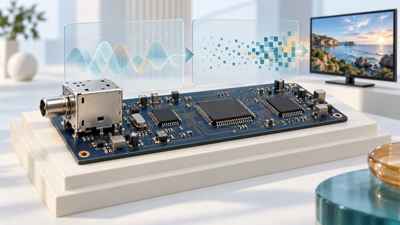
A digital television receiver turns a radio-frequency signal into pictures through several distinct jobs: tuning, demodulation, error correction, program selection and audiovisual decoding. Reading those jobs separately makes a chipset specification much easier to interpret.
Follow a conventional satellite receiver from input to screen
This simplified flow describes a broadcast receiver using an MPEG transport stream. It shows functional stages; manufacturers may combine several stages in one chip. Satellite systems also include outdoor receiving equipment that supplies an appropriate signal to the indoor receiver.
- RF tuningSelect the frequency range and convert the wanted signal for the following circuitry.
- DemodulationRecover the transmitted symbols and timing from the received waveform.
- Error correctionUse the transmission’s coding to recover data within the correction system’s limits.
- Transport and service selectionIdentify and route the packets belonging to the chosen program, including its audio and other components.
- Audio/video decodingReconstruct sound and pictures from their compressed representations.
- Presentation and outputCombine the decoded content with graphics and captions, then deliver supported picture and sound formats.
Subscription reception also requires the service’s authorized access system. That dependency crosses hardware, software and account provisioning; a generic tuner specification cannot establish eligibility for a particular pay-TV service.
DVB’s coding and transport overview distinguishes satellite transmission standards from audiovisual coding specifications. DVB-S2 concerns the transmission side, while the audio/video coding requirements describe another part of the system. Its newer Native IP work also illustrates why an MPEG transport-stream diagram should be labeled with its scope rather than applied to every broadcast architecture.
What real data sheets reveal
STMicroelectronics’ STV6120 data brief describes a dual satellite tuner that converts RF to baseband. Its diagram places frequency selection and conversion in the tuner. The separate STV0913 brief describes a demodulator supporting DVB-S2, DVB-S and legacy signals, with error-correction functions and interfaces to a tuner and host.
The manufacturer’s historical ST-9160 decoder brief includes a receiver application diagram with tuner and demodulator components feeding a decoder. That arrangement makes the division of work visible. These documents are architectural examples, not a recommended bill of materials or a claim that the parts remain available.
A system-on-chip can integrate several functions, so counting physical packages is a poor way to count capabilities. Instead, locate the supported standards, input and output interfaces, software requirements and limits for each function. ST’s demodulator overview explicitly describes both standalone parts and integration into larger processors.
Read compatibility in layers
Swipe or focus the table and use the arrow keys to see all columns.
| Layer | Information needed | What it helps establish |
|---|---|---|
| Reception | Input range, transmission standard, modulation and supported operating limits | Whether the receiver can acquire the intended signal |
| Program handling | Transport format, service information and authorized conditional-access integration | Whether the selected service can be found and accessed |
| Decoding | Video codec, profile, level, resolution, frame rate and bit depth; audio format | Whether the compressed program can be reconstructed |
| Output | Interface, supported output modes, captions and audio routing | Whether the display and sound system receive a usable result |
Example: a lock indicator with no picture
Suppose an authorized test receiver locks to a DVB-S2 carrier and identifies a program, but its decoder supports only an older video codec than the program uses. The reception stages can succeed while video decoding fails. The next check is the stream’s codec and decoder capability, with logs or test equipment confirming the actual cause. Retuning the antenna cannot add a missing codec.
For an engineering review, write one row per required service: transmission parameters, transport, access requirements, video tuple, audio and output mode. Then attach a documented playback result for the complete build. A data-sheet checkbox supports component selection; a system test supports a claim about the finished receiver.
Continue with IPTV receiver architecture for the network-delivery side, or receiver selection and setup for an owner-focused guide.