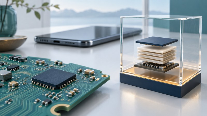
iNAND is a family of embedded flash-storage products. To interpret a part, identify the complete order code and its host interface, then examine capacity, firmware features and operating limits. A family name alone leaves too much unspecified for a design or replacement decision.
What “managed” adds to NAND
Managed flash combines NAND storage with a controller and firmware inside the storage device. The controller handles tasks such as error correction, address translation, wear leveling and bad-block management. KIOXIA’s UFS and e-MMC overview describes these functions; Micron’s NAND guide distinguishes raw, partially managed and fully managed approaches.
The host still controls filesystems, writes, power transitions and recovery policy. A managed chip simplifies the interface to the flash; the assembled product still needs validation. It also differs from a removable memory card: embedded packages are selected and integrated as board components.
Read interfaces at the part-family level
On a narrow screen, swipe the table or focus it and use the arrow keys.
| Example family | Documented interface | How to use the example |
|---|---|---|
| iNAND MC EU521 | UFS 3.1 | A 2020 product brief illustrates a specific generation |
| iNAND CL EM151 | e.MMC 5.1 | Identify the full ordering code and capacity |
| iNAND IX EU552 | UFS 3.1 | Check the industrial part’s applicable limits |
| iNAND IX EU752 | UFS 4.1 | Check host support and matching current documentation |
The EU521 example comes from its dated manufacturer product brief. The other examples are listed in Sandisk’s Industrial and IoT storage brochure. These references illustrate interface differences, not live stock or lifecycle guarantees.
e.MMC and UFS require their corresponding host support. Confirm package dimensions, ball map, power rails, signaling, boot requirements and firmware behavior in the exact part’s documentation. Similar capacity or package dimensions do not establish a drop-in replacement.
Separate a burst specification from the workload
The EU521 brief describes SmartSLC and UFS WriteBooster features and qualifies its performance by host, usage and capacity. Read such a rate as a measurement under stated conditions, then ask how long your own workload sustains it.
For a logger, capture the size and frequency of records, flush behavior, retention window, power interruptions and ambient conditions. For a media device, include recording bursts, background housekeeping and near-full operation. A short factory benchmark cannot answer all those questions.
Build a validation record for the assembled product
On a narrow screen, swipe the table or focus it and use the arrow keys.
| Area | Evidence to retain |
|---|---|
| Identity | Full order code, capacity, package and firmware revision |
| Host integration | Interface configuration, driver, boot and power-sequence requirements |
| Workload | Write sizes/rates, random access, capacity occupancy and latency needs |
| Reliability | Specified endurance/retention conditions and available health indicators |
| Interruption behavior | System-level tests and recovery acceptance criteria |
| Lifecycle | Supplier status, documentation revision and change-notification path |
Use a representative prototype with expendable data for power-interruption and endurance-related evaluation. Check acknowledged writes, filesystem recovery and application restart behavior against written acceptance criteria. A storage component’s advertised feature is only one part of the full power-loss path.
For an existing consumer device, use its supported backup, export or service route. Board-level replacement can depend on firmware, provisioning and encryption as well as soldering. Keep that access question separate from interpreting a chip’s capacity. The NAND explanation provides the cell-density and write-amplification background for reading the remaining specifications.