Updated October 9, 2026
Choose a microscope camera connection by checking mechanical fit, the optical path and the capture system. A tube that fits a port can still put the sensor in the wrong image plane or illuminate only part of it. Start with the microscope’s exact model and viewing head, then specify the camera and intended result.
Choose a camera route
| Route | How it works | Main compatibility questions |
|---|---|---|
| Phone over an eyepiece | The phone lens photographs the image presented by the eyepiece. | Clamp fit, accessible phone lens, alignment, spacing, support and camera-app behavior. |
| Interchangeable-lens camera | A designed projection or direct camera-port arrangement forms an image on the camera sensor. | Camera mount, projection optics, optical corrections, image circle, sensor position and support. |
| Dedicated microscope camera | A camera attaches to a compatible photo port or specified eyepiece-tube adapter. | Port interface, adapter magnification, sensor coverage, interface, driver and acquisition software. |
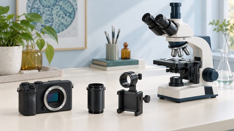
A trinocular head typically provides a photo port in addition to the eyepieces. Its light-path selector may share or redirect light. The Nikon optical-train reference shows how viewing and detector paths branch. A camera route can also be built around an eyepiece, but that is a different optical arrangement from placing a bare sensor directly at a port.
Write down the complete imaging chain
- Microscope: manufacturer, exact model, head model and the part number or drawing for its camera port.
- Optics: finite or infinity-corrected system, required relay/projection optics, and any additional magnification. Keep the manufacturer’s matched optical corrections in the chain.
- Camera: exact model, mount, sensor dimensions and supported capture modes. A phone needs its active lens position and the clamp’s clearances.
- Adapter: both interfaces, optical magnification or reduction, supported sensor sizes, required spacers and focus/parfocal adjustment.
- Capture device: operating-system version, available interface, driver and acquisition software, power requirements and file formats.
- Task: intended specimen, field of view, still images or video, need for measurements, and whether live sharing is important.
Ask a supplier to confirm this exact chain with part numbers and a compatibility document. A mount label such as C-mount describes a connection standard; successful imaging also depends on the adapter optics and sensor. Leica’s K3 camera specifications give different recommended adapters for stereo and compound configurations, illustrating why the microscope side matters. This is a compatibility example, not a recommendation to buy that camera.
Understand the adapter’s effect on the image
A reducing adapter can place a wider specimen field on a small sensor, provided its image coverage and optics are suitable. A larger sensor can reveal dark corners if the adapter’s usable image circle is too small. A stronger projection magnification can show a smaller field. The appropriate balance includes field coverage, optical detail and camera sampling; a megapixel count alone does not settle it. Nikon’s camera-matching tutorial connects objective, coupler and detector dimensions.
Include a clear photograph of the existing port and its label if the supplier asks for one. Avoid dismantling optical assemblies just to measure a hidden interface. Download the compatibility checklist (TXT) to keep answers and unresolved points in one place.
Test the connection before relying on it
- Assemble only the documented parts, with the support and tightening method specified by their manufacturers. Remove shipping or dust caps as instructed.
- Select a familiar prepared slide or other suitable test specimen. Establish a good eyepiece image and set the photo light path as directed.
- Open the supported acquisition software. Confirm a changing live image by moving the specimen slightly; then focus and save a test file.
- Check center and edges, dark corners, orientation and whether the saved file matches the intended field. Compare camera focus with the eyepiece and use the specified parfocal adjustment where available.
- Record a calibration image for the exact capture settings if measurements or scale bars are needed. Follow the scale-bar example.
- Disconnect and reconnect through the normal procedure, then repeat the test. Save the configuration, software version, adapter part numbers and calibration record.
Use symptoms to narrow the missing link
| Symptom | Check first | Follow-up |
|---|---|---|
| Software cannot see the camera | Supported interface, cable, power, driver and operating system. | Confirm the exact manufacturer software requirements; a physical connector does not establish software support. |
| Live image is dark | Caps, illumination and the photo-port selector. | Check the documented light path before changing exposure dramatically. |
| Center is bright, edges dark | Alignment for an eyepiece route; image coverage for a port route. | Confirm the specified sensor/adapter pairing with the supplier. |
| Camera never reaches focus | Sensor position, required relay optics and specified spacers. | Recheck the complete optical assembly before adding arbitrary extension tubes. |
| Phone changes field or focus unexpectedly | Automatic lens switching, zoom, focus and exposure settings. | Use stable supported camera settings and repeat calibration after a sampling change. |
Once the connection is dependable, work on illumination, focus and exposure with the photography guide. The parts diagram helps distinguish specimen focus from illumination controls. Keep the verified assembly documented so a later camera or software change can be checked against it.
Explore the Microscopes library
Browse all microscope guides and historical coverage. Sources are linked beside the explanations they support.