Updated October 9, 2026
A compound microscope makes small specimen details visible through a chain of optical components. In transmitted-light brightfield viewing, light passes through a thin specimen. The objective collects that light and the optical system forms an intermediate image; the eyepiece lets your eye view a magnified version of it. Use the sequence below to connect the parts to their jobs.
Read the optical sequence from bottom to top
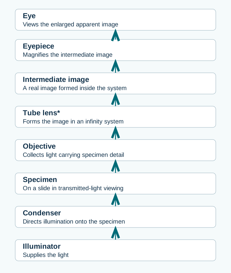
Open the full-size optical diagram. Nikon’s optical-train reference describes both finite and infinity-corrected arrangements. The specimen sits on the stage; the stage is a mechanical support, so it is not a separate image-forming element in this sequence.
Separate illumination from image formation
| Element | Contribution | A useful distinction |
|---|---|---|
| Illuminator | Provides light for viewing. | The brightness control changes the light level. |
| Condenser | Directs a cone of illumination toward the specimen. | Its adjustment changes illumination, while specimen focusing brings the specimen into view. |
| Objective | Collects specimen light and determines much of the available detail. | Its magnification and numerical aperture describe different properties. |
| Tube lens, when required | Forms an intermediate image from the infinity objective’s output. | It must belong to a compatible optical system. |
| Eyepiece | Magnifies the intermediate image for visual observation. | Increasing eyepiece power enlarges the image; the objective still limits available detail. |
The aperture diaphragm below the stage influences the illuminating cone and the balance of contrast and resolution. The field diaphragm, when present, limits the illuminated area. Closing either indiscriminately can degrade the view. Leica’s Köhler illumination explanation shows how these controls cooperate on a microscope equipped for that method. Some teaching microscopes have fixed or simplified illumination, so check the model’s instructions.
Calculate magnification and interpret the result
Resolution is the ability to distinguish nearby details. Numerical aperture describes how widely an objective accepts light from a specimen and helps determine resolving ability. Wavelength, preparation and illumination also matter. Nikon’s numerical-aperture explanation gives the optical basis. Higher magnification is useful when it makes available detail easier to see; enlarging an unresolved blur leaves the underlying uncertainty.
Field of view usually becomes smaller as objective magnification increases. With the same eyepiece field number and viewing optics, field diameter at the specimen is approximately field number divided by objective magnification. Illustrative calculation: a field number of 18 mm with a 10× objective gives about 1.8 mm; with a 40× objective, about 0.45 mm. Confirm the actual field by calibration when measuring. Nikon defines this field-of-view calculation.
Use a recognizable feature to understand orientation
An ordinary compound microscope forms an inverted intermediate image. Many teaching arrangements therefore show apparent image motion opposite to the direction you move the slide. Try a prepared letter slide at low power and observe the actual relationship on your instrument; camera software or additional optics can rotate or flip a displayed image.
Center the feature before increasing magnification. With a smaller field, an off-center feature may disappear even though the slide has barely moved. Refine focus rather than making a large blind adjustment toward the slide.
Recognize which design you are looking at
An upright compound microscope places the objectives above the specimen. An inverted microscope places them below. A stereo microscope uses separate viewing paths to create a depth impression and commonly gives more room for larger solid objects. Nikon’s stereomicroscopy introduction explains that design. The presence of two eyepieces alone does not identify a stereo microscope.
Historical stands may use a mirror and an adjustable drawtube; many modern systems use an internal light source and fixed compatible optics. Treat the drawing as a map of functions, then identify the corresponding components on your instrument. For the actual knobs and a recovery sequence, continue to microscope parts and controls. For a camera branch, use camera-adapter compatibility.
Explore the Microscopes library
Browse all microscope guides and historical coverage. Sources are linked beside the explanations they support.