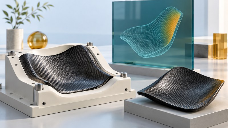
Composite process simulation is useful when a defined prediction can guide a manufacturing decision. Specify that decision first, document the material and process inputs, and compare the relevant output with measured parts. A credible result includes where the model has been tested and where its use still depends on assumptions.
Choose a process question and observable output
For forming, the question might concern wrinkles or local thickness. For resin infusion, it might concern fill progression or a suspected dry region. For curing and release, it might concern temperature history or final distortion. Pick outputs that the physical trial can actually observe, with defined locations, timing and units.
Keysight describes PAM-COMPOSITES as covering forming, injection or infusion, curing and distortion, with transfer of manufacturing information between stages. Treat these as documented software capabilities. Accuracy for a particular material, tool and route must be established with the applicable model and evidence.
Write a decision statement such as “compare two blank-holder configurations for this layup within the tested temperature range.” Identify the person who will act on the result and the consequence of a wrong prediction. This bounds the validation work more clearly than a general request to simulate the part.
Keep model inputs traceable
On a narrow screen, scroll the table horizontally. Keyboard users can focus it and use the arrow keys.
| Input group | Examples to record as applicable | Useful physical comparison |
|---|---|---|
| Material | Layup, orientation, lot, constitutive data and characterization conditions | Independent material tests within the modeled range |
| Tool and contact | Tool revision, restraints, friction and contact assumptions | Observed draw-in, slip or local forming behavior |
| Process history | Temperature, pressure, flow or machine motion history | Recorded trial histories at identified locations |
| Numerics | Solver version, mesh, time stepping and convergence controls | Stability of the decision-relevant output under refinement |
Separate measured inputs from fitted parameters and assumed values. Preserve the source, units, applicable range and uncertainty for each consequential input. A default value deserves an explicit review when the result is sensitive to it. In a chained model, also check how thickness, fiber orientation or cure information is transferred between stages.
Run numerical checks before interpreting a physical mismatch. Review warnings, conservation checks where applicable, and changes in the chosen output with mesh or time-step refinement. A stable solver result can still depend on an unsuitable physical model.
Reserve evidence for independent comparison
Use calibration data to fit parameters and reserve other relevant trials for validation. Reusing the same measurements for both tasks makes it harder to judge prediction beyond the fitted cases. Plan sufficient measurements to capture location-dependent behavior and normal trial variability.
NIST's report on verification, validation and uncertainty in CFD provides a general credibility framework: physical modeling, analyst competence, numerical verification, validation and uncertainty all matter. Its scope is computational fluid dynamics; it supplies methodological context here, not validation of a composite solver.
Fictional held-out comparison: predicted thickness at one defined location is 1.80 mm; measured thickness is 1.70 mm. Prediction minus measurement is +0.10 mm. The absolute relative difference, using the measurement as denominator, is 0.10 ÷ 1.70 × 100 = 5.88%, rounded.
That number describes one location. Evaluate measurement uncertainty, the spatial pattern and the pre-agreed decision threshold. A correct average could conceal a poor prediction in the critical corner.
State what the model can support
Vary uncertain inputs over justified ranges and inspect whether the preferred decision changes. If two configurations exchange rank within plausible input uncertainty, use further characterization or trials to resolve the choice. Report the range and the unresolved assumptions with the nominal result.
Finish with a model-use statement naming the material, layup, geometry family, process range and validated outputs. Record exclusions and revalidation triggers such as a new resin, fabric architecture, tool or solver behavior. Keep calibration files, validation observations and the released model together. For the associated design data, use a reproducible CAD review before building the analysis.
Use the working record
Download the editable composite model validation. Save a copy, complete the actual requirements and evidence fields, and review open issues with the responsible owner. The plain-text record includes instructions, units where needed, the fictional example, and source references.