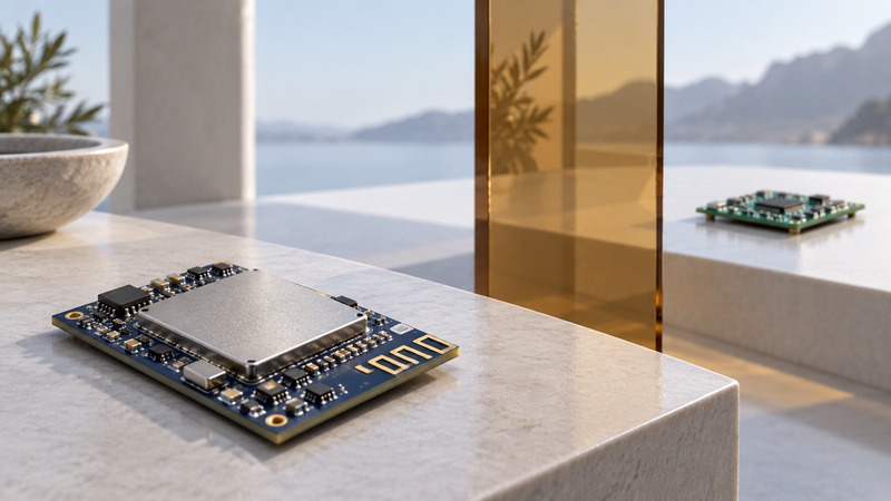
A Bluetooth transceiver sends and receives radio signals. Its usefulness depends on the radio mode, antenna, surrounding hardware, software and device at the other end. To compare designs, read specifications under matching conditions and test the complete installed link in both directions.
Place the transceiver in the complete system
The radio converts between electrical signals and over-the-air communication. Digital controller functions handle lower-level Bluetooth behavior, while host software and application services decide what the product actually does. These roles may be integrated into one system-on-chip or split across components. A module can add supporting circuitry and an antenna around a chip.
The Bluetooth SIG technology overview separates Bluetooth Classic and LE radio modes and capabilities. Match the intended peer and function first. A newer version label alone does not establish support for the audio profile, sensor service or firmware interface your application needs.
For product selection, use the module integration guide. The purpose here is to interpret radio behavior and the evidence behind a range claim.
Compare like-for-like radio specifications
On small screens, scroll the table sideways to read all columns.
| Specification | Meaning | Comparison requirement |
|---|---|---|
| Transmit power, dBm | Radio output power relative to 1 milliwatt | Same configured mode and allowed operating conditions. |
| Receiver sensitivity, dBm | Input level at a defined error-performance threshold | Same PHY, data rate and error criterion. |
| Antenna gain, dBi | Directional gain relative to an ideal isotropic antenna | Installed antenna, orientation and enclosure. |
| Current consumption, mA | Power-system load in the stated operating state | Same transmit power, duty cycle and supply conditions. |
The Bluetooth SIG range explanation identifies radio mode, sensitivity, transmit power, antenna gain and path loss as relevant factors. More transmit power can increase energy use; enclosure materials, placement and obstacles change the installed result. Record the conditions instead of comparing two isolated headline numbers.
Work through a hypothetical link margin
A simple power budget adds gains and subtracts losses. Silicon Labs’ RF-performance training discusses output power and sensitivity together and emphasizes the returning link. Use a budget to organize assumptions before measurement.
Illustrative numbers, not a product specification
Assume transmit power of +4 dBm, transmit and receive antenna gains of −2 dBi each, other losses of 3 dB, path loss of 70 dB, and receiver sensitivity of −96 dBm for the selected mode.
Received power = 4 − 2 − 2 − 3 − 70 = −73 dBm.
Margin above sensitivity = −73 − (−96) = 23 dB.
If an additional obstacle contributes 15 dB of loss, received power becomes −88 dBm and the remaining margin is 8 dB.
The example uses invented but explicitly stated assumptions. Its positive margin is arithmetic headroom relative to the chosen threshold; it does not establish a distance, packet-delivery rate or performance in interference. Repeat the budget in the reverse direction using that transmitter and receiver’s values. A strong outward link can coexist with a weaker return link.
Test the installed link and the actual workload
- Record both devices, firmware, radio mode, configured power, antenna placement and enclosure.
- Choose the required task and success criteria: for example, complete sensor records within a stated delay. Keep the payload and sending interval fixed during comparisons.
- Establish a close-range baseline, then test representative locations, orientations and obstructions in the intended environment.
- Log received and missing records, delay, reconnect behavior and battery use where measurable. Treat RSSI as one observation alongside successful application behavior.
- Repeat with the enclosure fitted and ordinary nearby radio activity present. Change one placement or configuration variable at a time.
Use supported configuration and manufacturer antenna guidance. Follow applicable product and radio requirements; increasing power arbitrarily is not a substitute for a well-integrated antenna. Report the tested route, conditions and workload with any range result so another person can interpret it.
Keep a record and continue
Download the working checklist (plain text). Record your equipment, evidence and next action in its blank fields.
- Select and integrate a Bluetooth module
- Build a documented BLE demonstration
- Explore all Bluetooth guides
Researched and updated September 18, 2026. The link-budget values are hypothetical, not measured specifications. No range or regulatory approval is claimed for a physical design.