A modern vehicle is a network of physical systems made observable through sensors. Some measurements are familiar: wheel speed, coolant temperature, fuel pressure and oxygen in the exhaust. Others are newer or newly important: battery-cell voltage, busbar current, refrigerant pressure, rotor angle, driver gaze, seat occupancy, road-edge geometry and the distance, velocity and height of objects around the vehicle.
No single number captures how many sensors a vehicle contains because manufacturers count integrated modules, sensing elements and derived “virtual sensors” differently. The important fact is architectural: almost every significant function depends on measurements. Brakes estimate slip at each wheel. Airbags identify a crash within milliseconds. Electric vehicles estimate energy and thermal limits from thousands of cell-related observations. Driver-assistance computers combine cameras and radar to decide whether an object is a pedestrian, vehicle, sign, lane boundary or harmless roadside structure.
The sensor itself is only the beginning. Packaging must survive vibration, water, salt, fuels, electromagnetic interference and temperature cycling. Signal conditioning must distinguish a meaningful change from noise. Software must diagnose open circuits, drift, blockage and implausible combinations. Calibration must remain valid after assembly and repair. Safety engineering determines what the vehicle should do when a measurement is missing or uncertain.
The major sensor domains
| Vehicle domain | Representative sensors | Functions enabled |
|---|---|---|
| Combustion powertrain | Crank and cam position, air mass, manifold pressure, fuel pressure, knock, oxygen and exhaust temperature | Injection, ignition, boost, combustion control, diagnostics and emissions compliance |
| Electric drive and battery | Cell voltage, current, temperature, insulation, pack pressure, rotor position and coolant flow | State estimation, charging, torque control, thermal protection and high-voltage safety |
| Chassis and motion | Wheel speed, steering angle, acceleration, yaw rate, suspension travel, brake pressure and tire pressure | ABS, stability control, steering, damping, traction and vehicle-dynamics estimation |
| Occupant protection | Impact acceleration, door pressure, seat weight, belt status and rollover motion | Airbag and pretensioner timing, restraint adaptation and post-crash response |
| Exterior perception | Cameras, radar, lidar and ultrasonic sensors | Emergency braking, lane support, adaptive cruise, blind-spot monitoring and parking |
| Localization | GNSS, inertial measurement, wheel odometry, steering angle and map-referenced landmarks | Navigation, lane-level positioning and continuity through tunnels or urban canyons |
| Interior and comfort | Cabin camera, radar, microphones, temperature, humidity, air quality, light and rain sensors | Driver monitoring, occupant detection, climate control, voice interaction and automatic lighting |
| Body and convenience | Hall switches, capacitive touch, current sensing, anti-pinch and position sensors | Doors, seats, windows, wipers, lighting, access and power closure control |
The physical principles behind automotive sensing
Different measurements demand different transduction methods. Mature sensing principles continue to improve through semiconductor integration, better packaging, digital interfaces and on-device diagnostics.
| Principle | What it detects | Automotive examples |
|---|---|---|
| Resistive and piezoresistive | Resistance change caused by strain, pressure or temperature | Pressure diaphragms, strain gauges, shunts and thermistors |
| Capacitive | Change in spacing, area or dielectric material | MEMS accelerometers, pressure sensors, touch controls and occupant detection |
| Inductive and variable reluctance | Change in magnetic coupling or reluctance | Crank speed, resolver rotor position and robust proximity measurement |
| Hall effect and magnetoresistive | Magnetic field magnitude or direction | Pedal, throttle, steering, motor position, wheel speed and current measurement |
| Piezoelectric | Charge generated by mechanical stress | Knock, vibration, force and ultrasonic transducers |
| Optical | Intensity, color, image, time of flight or interruption | Cameras, lidar, rain/light sensing, encoders and fiber-optic sensing |
| Radio frequency | Reflected electromagnetic waves and phase | 76–81 GHz radar, tire-pressure radio links and cabin radar |
| Electrochemical and ceramic | Gas concentration or ion activity | Oxygen, nitrogen oxide, ammonia, particulate and air-quality sensing |
| Thermal | Heat transfer or infrared radiation | Air-mass flow, temperature, thermal cameras and occupant presence |
| Acoustic | Pressure waves and time of flight | Ultrasonic parking, microphones, leak detection and road-noise control |
Engine-management sensors
Combustion engines depend on precise timing and air-fuel control. Crankshaft and camshaft sensors identify rotational speed and phase so the controller can schedule injection, ignition and valve events. Variable-reluctance sensors are robust and generate a signal from a toothed wheel; Hall-effect and magnetoresistive sensors can provide a clean digital output down to zero speed and encode direction.
Manifold absolute-pressure sensors measure engine load, while mass-air-flow sensors estimate the air entering the engine. Throttle and accelerator-pedal sensors report commanded airflow and driver demand, usually with redundant signal tracks. Intake-air, coolant and oil-temperature sensors support fueling, protection and thermal management.
Direct injection requires pressure sensing across low- and high-pressure fuel circuits. Turbocharged engines add boost pressure, charge-air temperature, turbo position and sometimes exhaust-pressure sensing. Knock sensors detect block vibration associated with abnormal combustion, allowing ignition timing to approach efficient limits without engine damage.
Many quantities are estimated rather than directly measured. Airflow can be inferred from manifold pressure, temperature, displacement and speed. Cylinder torque can be estimated from tiny crank-speed variations. These software-derived or virtual sensors reduce hardware or add information that is difficult to measure in production, but their accuracy depends on a calibrated physical model and trustworthy inputs.
Exhaust and emissions sensing
A narrowband oxygen sensor switches sharply near stoichiometric combustion; a wideband lambda sensor measures a broader range and supports precise gasoline and diesel control. These sensors use oxygen-ion-conducting ceramic at high temperature, with integrated heaters bringing them quickly into operation.
Diesel and lean-burn aftertreatment adds nitrogen-oxide sensors before or after selective catalytic reduction, exhaust-temperature sensors, differential-pressure measurement across particulate filters and particulate sensors that verify filter performance. Ammonia sensing or estimation helps manage urea dosing and detect slip. Gas sensors operate in a harsh stream containing soot, condensate, sulfur and rapid temperature changes, so contamination resistance and heater control are part of the design.
Onboard diagnostics compare sensors, models and actuator responses. A pressure rise across a particulate filter should agree with exhaust flow and soot loading. Oxygen-sensor behavior can reveal catalyst deterioration. A fault code is therefore often the conclusion of a diagnostic test rather than a direct statement that one named sensor has failed.
Electric-vehicle battery sensing
An electric vehicle battery is a tightly monitored electrochemical system. Cell-monitoring circuits measure individual or grouped cell voltages; temperature sensors are distributed through modules and cooling paths; pack-current sensors measure charge and discharge; high-voltage measurement verifies bus conditions. The battery-management system uses these observations to estimate state of charge, available power, state of health and safe charging limits.
State of charge cannot be measured directly like fuel level in a transparent tank. The controller integrates current over time, corrects that estimate using voltage and temperature behavior, and applies a battery model. Aging, cell imbalance and temperature gradients make the problem harder. State of health similarly combines capacity, internal resistance and usage history rather than one sensor reading.
Current measurement
A precision shunt measures the voltage drop across a known resistance and can provide high accuracy, but it sits electrically in the current path and needs isolated measurement electronics at high voltage. Hall-effect, fluxgate and magnetoresistive sensors measure the magnetic field around a conductor, providing galvanic isolation with different tradeoffs in offset, bandwidth, size and cost.
Thermal-runaway detection
Temperature remains essential, but a failing cell can develop locally before a remote thermistor responds. New pack designs may add pressure, gas, humidity, acoustic or particle sensing to detect venting and propagation earlier. Infineon describes battery-pack pressure as an emerging use for automotive MEMS pressure sensors. These measurements complement—not replace—cell voltage, current, isolation monitoring, mechanical barriers and thermal design.
Electrical isolation and crash safety
Insulation-monitoring devices detect leakage between the high-voltage system and chassis. Pyrotechnic disconnect control depends on crash sensors and high-voltage state. Contactors need position or electrical feedback so the controller knows whether the pack is connected. During service, diagnostic measurements must establish that stored voltage has fallen to a safe level.
Even electrified vehicles retain a low-voltage battery whose condition supports computers, locks, contactors and safety systems. An electronic battery sensor measures current, voltage and temperature and estimates charge and health. Bosch's 12-volt battery sensor illustrates how sensing and embedded algorithms have merged into one intelligent module.
Electric motors, inverters and charging
Traction motors require rotor-position information so the inverter can align current with the magnetic field. Resolvers are robust inductive devices common in demanding drives. Hall or magnetoresistive position sensors offer compact alternatives, while sensorless algorithms infer position from voltage, current and motor behavior over parts of the operating range.
Phase-current sensors, DC-link voltage measurement and temperature sensors protect power semiconductors and control torque. Bearing, winding and coolant temperatures constrain continuous output. Accelerometers and acoustic sensing can support condition monitoring for bearings or gears.
Charging adds connector-temperature, proximity, pilot-signal, current, voltage and isolation measurements. Fast charging can be limited by the hottest cell, connector or conductor rather than average battery temperature. Accurate sensing allows the system to use available thermal margin without exceeding component limits.
Thermal management becomes a sensing network
A combustion vehicle has several thermal measurements; an EV coordinates battery, motor, inverter, cabin and ambient heat through coolant and refrigerant loops. Temperature and pressure sensors monitor evaporators, condensers, chillers and heat exchangers. Flow or pump-speed feedback verifies circulation. Humidity and windshield-temperature sensing prevent fogging without excessive energy use.
Thermal management affects range, fast charging, power and battery life. Bosch's overview of EV thermal management shows why battery and e-axle conditions must be controlled alongside cabin comfort. The controller often estimates unmeasured component temperatures from a thermal model, using physical sensors to anchor it.
Chassis sensors and vehicle dynamics
Anti-lock braking begins with wheel-speed sensors. Electronic stability control adds steering angle, yaw rate, lateral acceleration and brake-pressure data to compare the driver's intended path with actual motion. If the vehicle begins to understeer or oversteer, brakes and powertrain torque can be adjusted at individual wheels.
Wheel-speed sensors now support far more than ABS. Their pulse timing contributes to tire-pressure estimation, low-speed parking motion, odometry and automated-driving localization. Active magnetic sensors detect nearly zero speed and direction, while encoded wheel bearings integrate the magnetic target.
Steering systems measure wheel angle, steering-wheel position, torque and motor position. Brake-by-wire adds pedal travel or force, hydraulic pressure, actuator position and motor current. Redundant channels and diverse sensing principles help detect a common failure before control authority is lost.
Active suspension uses body accelerometers, wheel accelerometers, ride-height or suspension-position sensors and sometimes road-preview cameras. The controller estimates body heave, pitch and roll, then adjusts dampers, springs or actuators. Tire-road friction remains only indirectly observable, so control systems infer it from slip, acceleration, wheel torque and environmental cues.
Tire sensing advances beyond a warning light
Direct tire-pressure monitoring places a pressure sensor, temperature sensor, accelerometer, radio and battery in each wheel. Indirect systems infer a low tire from wheel-speed differences or vibration signatures, avoiding wheel electronics but depending on calibration and driving conditions.
Newer smart-tire concepts measure temperature distribution, acceleration at the tire carcass, tread condition, load or deformation. These signals could improve pressure correction, road-friction estimation, tire wear prediction and fleet maintenance. The challenge is powering, packaging and communicating from a rotating component that experiences impact, heat, centrifugal force and tire service.
Crash sensing and occupant protection
The restraint controller uses central accelerometers and satellite acceleration or pressure sensors near the vehicle perimeter. Door-cavity pressure can reveal a side impact quickly because intrusion changes enclosed pressure before crash energy reaches a central sensor. Rollover detection combines angular rate and acceleration.
Deployment logic distinguishes crash direction, severity and timing, then selects airbags and belt pretensioners. Seat-position, belt-buckle and occupant-classification sensors help adapt the response. The system must decide in milliseconds, yet avoid deployment during potholes, door slams or non-crash events.
New U.S. seat-belt reminder requirements further expand occupant-state awareness. Enhanced front-seat warning requirements begin for new vehicles in September 2026, with rear-seat requirements following in September 2027. Implementation can involve buckle status, seat occupancy and logic designed to avoid both missed occupants and persistent false reminders.
Cameras: semantic richness with environmental sensitivity
Vehicle cameras transform light into pixel arrays that software interprets. A forward camera recognizes lanes, road edges, signs, signals, vehicles, pedestrians and cyclists. Surround cameras support parking and low-speed 360-degree views. Rear and mirror-replacement cameras extend visibility. Infrared-sensitive cabin cameras monitor the driver in darkness.
Cameras provide color, texture and classification detail unavailable from basic radar or ultrasound. Their limitations include glare, darkness, fog, snow, dirty lenses, low contrast and the challenge of converting a two-dimensional image into reliable depth. Stereo cameras infer distance from parallax; monocular systems estimate depth from learned and geometric cues; structure-from-motion uses changing viewpoint.
High dynamic range helps preserve detail in bright sky and dark shadows. Flicker mitigation addresses LED traffic lights and signs. Image-signal processors correct lens shading, defective pixels, noise and color before neural networks analyze the scene. A well-performing imager requires calibrated optics, heating or cleaning, stable mounting and software trained on relevant conditions.
Automotive radar: direct range and velocity
Modern automotive radar generally operates in the 76–81 GHz band. Frequency-modulated continuous-wave signals measure range from beat frequency, relative velocity from Doppler shift and direction through multiple transmit and receive antennas. Front radar supports adaptive cruise and emergency braking; corner radars cover blind spots, cross traffic, lane changes and cut-in vehicles.
Radar is valuable in darkness and many adverse-weather conditions and measures radial velocity directly. Traditional sensors had limited angular and elevation resolution, making closely spaced objects or overhead structures difficult to distinguish. Larger virtual antenna arrays, better radio-frequency chips and more computing are producing imaging or “4D” radar point clouds with range, azimuth, elevation and velocity. Continental's current radar portfolio includes high-resolution 4D long-range devices and lower-cost satellite radars.
Radar still encounters multipath reflections, interference, ghost targets and weak returns from some objects. Mounting behind painted plastic seems simple, but bumper thickness, paint, repair materials, ice and bracket angle alter performance. Calibration after collision repair matters.
Lidar: precise three-dimensional ranging
Lidar sends laser light and measures its return to create a three-dimensional point cloud. Pulsed time-of-flight systems measure travel time; frequency-modulated continuous-wave lidar can also extract relative velocity from optical frequency shift. Mechanical scanning, rotating assemblies, microelectromechanical mirrors, optical phased arrays and flash illumination represent different architectures.
Lidar's precise geometry can identify free space, curbs and object shape without relying on ambient illumination. Limitations include cost, range on dark or low-reflectivity surfaces, weather, contamination and the reliability of a scanning or high-power optical system. Near-infrared and longer-wavelength designs differ in detector technology, eye-safety constraints and atmospheric behavior.
Valeo's SCALA lidar is an example of an automotive-qualified scanning system used in production Level 3 applications. Other manufacturers are developing solid-state and hybrid designs. Lidar is not mandatory for every driver-assistance architecture, but it provides an independent geometric measurement valued in higher-automation systems.
Ultrasonic sensors remain useful at close range
An ultrasonic transducer emits sound above human hearing and measures the echo delay. These sensors are inexpensive and effective for parking distances around bumpers, where cameras may lack depth and radar once had limited close-range resolution.
Soft, angled or acoustically absorbent surfaces can return weak echoes. Heavy rain, air temperature, contamination and interference from other sensors affect results. Some newer parking architectures combine high-resolution radar with cameras and reduce the ultrasonic count, but ultrasound remains a mature and practical option.
Driver and occupant monitoring
A driver-monitoring camera observes gaze direction, eyelid closure, head pose and facial cues to estimate attention and drowsiness. Infrared illumination allows operation at night and behind many eyeglasses, though sunglasses, occlusion, individual variation and privacy require careful handling. Steering-input monitoring alone cannot reliably establish where the driver is looking.
Occupant-monitoring cameras estimate seat position, body pose and whether a child or object is present. Short-range radar can detect motion and, in favorable conditions, subtle respiration without an optical image. It is promising for rear-seat reminders, child-presence detection and occupant classification under blankets or in darkness.
Interior monitoring creates sensitive data. Good designs process images locally when possible, retain only what the function needs, protect diagnostic access and communicate clearly what is collected. A safety system should also state when blocked or unable to assess the driver.
Comfort, air quality and human-machine interfaces
Cabin temperature is only one climate input. Humidity, solar load, outside temperature, evaporator temperature, refrigerant pressure and sometimes carbon dioxide or volatile-organic-compound sensors help the HVAC system balance comfort, fog prevention, energy and air quality. Particulate sensing can manage filtration or recirculation in polluted environments.
Ambient-light and rain sensors often share an optical module near the windshield. The rain channel detects changes in internally reflected light as water contacts the glass; the light channel controls lamps and display brightness. Capacitive and force sensing supports touch panels and steering-wheel hands-on detection, while microphones form directional arrays for voice commands, calls and active noise control.
Contactless access uses low-frequency radio, Bluetooth or ultra-wideband ranging to distinguish a key or phone approaching the vehicle from one relayed at a distance. UWB's time-of-flight measurement can improve secure localization, although the complete system still needs cryptographic authentication.
Localization requires more than GPS
Global navigation satellite systems provide absolute position and time but can be blocked, reflected or deliberately disturbed. Urban canyons create multipath; tunnels remove satellite visibility. High-precision systems use corrections, multiple constellations and multiple frequencies, yet still need independent motion estimation.
An inertial measurement unit combines accelerometers and gyroscopes to track short-term motion. Wheel speeds and steering angle contribute odometry. Cameras and radar match lanes, signs, poles, guardrails or other landmarks to maps. Sensor fusion bridges gaps and detects disagreement. Bosch's localization overview describes inertial sensing as the relative-position layer used when satellite or surrounding information is unavailable.
Inertial errors accumulate over time, wheels slip and maps age. A localization system therefore estimates uncertainty, not just coordinates. The driving function must know when lane-level confidence has degraded below its operating requirement.
Sensor fusion: complementary measurements, not a vote
A camera may classify a pedestrian while radar measures range and closing speed. Lidar may confirm shape and free space. Ultrasonic sensors cover the final parking distance. Inertial and wheel measurements stabilize object tracks as the vehicle moves. Fusion aligns these observations in time and space, associates them with the same physical object and updates estimates of position, velocity, class and uncertainty.
Fusion can occur at several levels. Raw fusion combines minimally processed measurements but requires high bandwidth and tight synchronization. Feature fusion combines detections or learned features. Object-level fusion merges independently tracked objects and is easier to modularize but may discard useful information.
Diversity is valuable because sensors fail differently. Radar can measure velocity through darkness; a camera can read a signal's color; lidar supplies precise geometry. Yet fusion does not guarantee truth. Two sensors can share an obstruction, mounting error, timestamp fault or flawed assumption. Bosch's discussion of radar and camera fusion illustrates the complementary strengths and the role of software in reducing false warnings.
ADAS, automated driving and regulatory pressure
Driver-assistance functions range from momentary warnings and emergency intervention to continuous control of speed and steering. At SAE Level 2, the driver remains responsible for monitoring the road even when both longitudinal and lateral control are active. Higher levels shift the driving task only within a defined operational design domain.
Automatic emergency braking has made forward perception a mainstream safety system rather than a premium option. U.S. FMVSS No. 127 requires qualifying light vehicles to meet vehicle and pedestrian AEB performance requirements, with manufacturer compliance scheduled for September 1, 2029. The rule is performance-based rather than prescribing one sensor combination; manufacturers may use camera, radar or fused architectures that satisfy the tests.
Consumer-assessment programs are also testing more difficult interactions involving pedestrians, cyclists, motorcycles, turning and nighttime conditions. These demands drive wider fields of view, improved radar resolution, better low-light imaging and more representative validation data.
Calibration is part of the vehicle repair
Perception sensors measure relative to a coordinate frame. If a camera, radar or lidar is shifted by a small angle after windshield replacement, bumper repair, alignment or suspension work, an object can be placed in the wrong lane or at the wrong height. Static calibration uses precisely located targets in a controlled bay. Dynamic calibration learns parameters while driving under specified road conditions. Some vehicles require both.
Calibration is not a universal button press. Ride height, tire pressure, wheel alignment, load, floor level, lighting, target distance and diagnostic procedure may matter. Replacement glass, brackets and bumper materials must satisfy the optical or radio-frequency design. A diagnostic trouble code clearing successfully does not prove geometric calibration.
Functional safety and intended-function safety
ISO 26262 addresses hazards caused by malfunctioning electrical and electronic systems. Sensor development may include redundant elements, plausibility checks, watchdogs, reference voltages, communication protection, latent-fault detection and a defined safe response. Automotive Safety Integrity Levels guide the rigor according to risk.
A sensor can work exactly as designed and still be insufficient. A camera may be blinded by low sun; radar may merge adjacent targets; a neural network may misclassify an unusual object. ISO 21448, Safety of the Intended Functionality, addresses unreasonable risk from performance or specification insufficiencies when no conventional fault exists. Its SOTIF framework is central to perception-based functions.
The safe response depends on the function. A failed outside-temperature sensor may default climate control. Loss of a wheel-speed signal disables ABS enhancements and warns the driver. A blocked forward camera may suspend lane assistance. An automated-driving system may require redundant sensing and a minimal-risk maneuver rather than immediate transfer to an unprepared driver.
Diagnostics, drift and sensor health
Automotive diagnostics look for electrical faults, timing errors, implausible values and disagreement with models. A temperature reading outside physical limits suggests an open or short circuit. A steering angle inconsistent with yaw rate and wheel speeds may indicate calibration loss. A radar whose return pattern changes after snow accumulation can report blockage.
Drift is harder than a complete failure. Pressure diaphragms age, camera brackets move, lenses haze and magnetic sensors encounter stray fields. Cross-domain checks and long-term trend analysis can identify gradual degradation. Predictive maintenance is strongest when a sensor-health change connects to a service action rather than merely producing another alert.
Self-cleaning is becoming part of perception design. Heated lenses, hydrophobic coatings, air jets, washer fluid and wipers keep optical surfaces usable. Radar hides behind bumpers but may need heating against ice. A beautifully specified sensor that cannot see after ordinary road contamination is not a complete automotive solution.
Networking and time synchronization
Simple sensors may produce analog voltage, frequency or SENT digital signals. LIN connects low-cost body devices. CAN and CAN FD carry robust control messages. Automotive Ethernet transports high-bandwidth camera, radar and lidar data toward centralized computers. Local sensor interfaces include PSI5 for restraint applications and specialized high-speed serial links for imagers.
Timestamp accuracy is essential. At highway speed, a delay of tens of milliseconds moves the vehicle and surrounding objects significantly. Sensor data must be synchronized, communication latency bounded and stale measurements detected. Centralized vehicle computers reduce duplicated processing but make network quality, power architecture and software isolation more critical.
Cybersecurity reaches the sensing layer
A sensor value can be wrong because of a physical fault, environmental limitation or malicious input. GNSS can be jammed or spoofed. Cameras may encounter adversarial patterns. Radar interference can be intentional or accidental. Tire-pressure and access signals can be intercepted if protocols are weak.
Defenses include authenticated communication, secure boot, protected calibration, anomaly detection, diversified localization and robust fallback. Cybersecurity and functional safety intersect but are not interchangeable: safety asks what happens when information is wrong; security asks how an attacker could make it wrong or misuse the data.
Development, simulation and validation
Sensor development combines component characterization, vehicle testing, simulation, proving grounds and controlled laboratories. Hardware-in-the-loop systems stimulate control units with simulated sensor signals. Vehicle-in-the-loop and scenario testing expose complete systems to repeatable targets. Radar target simulators, camera projection systems and lidar simulation test dangerous or rare events without relying solely on road miles.
Data quality matters as much as volume. A perception system needs examples across weather, lighting, road geometry, countries, body types, mobility aids, vehicle classes and unusual objects. Ground truth must be accurate enough to evaluate small distance or timing errors. Scenario coverage and safety argument are more meaningful than a raw count of miles driven.
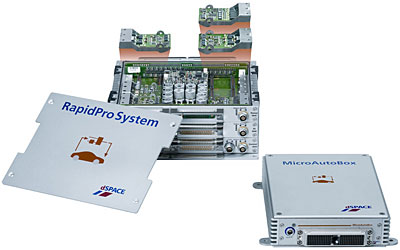
The dSPACE RapidPro system described in the original 2005 article belonged to this development layer. Its signal-conditioning and actuator modules connected real vehicle hardware to rapid-control-prototyping computers for engine, transmission, body and chassis algorithms. Current systems retain that need while adding high-voltage interfaces, automotive Ethernet, real-time sensor simulation, virtual electronic control units and automated scenario testing.
Emerging directions
- Imaging radar adds elevation and finer angular separation while moving more processing into the sensor.
- Solid-state and FMCW lidar seek smaller packages, lower cost and direct velocity measurement.
- Event cameras report brightness changes rather than complete frames, offering low latency and high dynamic range for selected tasks.
- Thermal imaging can improve detection of people and animals at night, though cost and classification remain considerations.
- Cabin radar detects presence and motion without producing a conventional optical image.
- Smart tires move load, wear and road-contact estimation closer to the physical interface.
- Battery gas, pressure and acoustic sensing aims to identify cell failure before heat reaches conventional sensors.
- Sensor-edge AI reduces bandwidth by transmitting objects or features, but moves validation and update responsibility into the sensor module.
- Software-defined sensing allows processing improvements after sale while requiring controlled calibration, cybersecurity and regression testing.
Depth matters more than sensor count
A vehicle does not become safe or intelligent merely by adding more sensors. Every added measurement introduces mounting, wiring, power, calibration, diagnostics, software, service and cybersecurity responsibilities. Redundant sensors add value only when their failures are sufficiently independent and the system knows how to arbitrate disagreement.
The modern achievement is depth: physical sensing elements packaged for years of road exposure; electronics that condition and digitize weak signals; networks that preserve timing; algorithms that estimate unmeasured states; fusion that represents uncertainty; diagnostics that recognize degradation; and controls that fail in a planned way.
From a crankshaft tooth passing a magnetic pickup to a lidar point cloud describing a city intersection, automotive sensing converts the physical world into decisions. It is the foundation beneath cleaner powertrains, stable handling, occupant protection, electric range, driver assistance and every credible path toward greater vehicle automation.