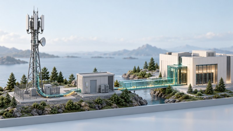
A 3G network combines radio sites, transport links, service-control systems and connections to other networks. The tower is the visible part. Behind it, equipment manages who can connect, how users move between cells, and where their calls and data go.
This guide follows a classic UMTS connection, compares the CDMA2000 packet-data path, and separates coverage from capacity. Use it to interpret a network diagram or ask better questions about a slow connection.
Follow a classic UMTS call and data session
A handset, called User Equipment or UE in the specifications, communicates with a Node B base station. A Radio Network Controller (RNC) manages radio resources and connections across its part of the access network. Together, Node Bs and RNCs form UTRAN, the UMTS Terrestrial Radio Access Network.
- Handset / UERadio and subscriber equipment
- Node BRadio transmission and reception
- RNCRadio resource and connection control
Traditional voice
RNC → MSC functions → other telephone networks
The circuit-switched core handles conventional operator voice service.
Packet data
RNC → SGSN → GGSN → external data network
The packet core manages the session and carries traffic toward an internet or private-network service.
This is a simplified classic architecture. Authentication databases, detailed signaling and later-release alternatives are omitted.
3GPP TS 25.401, Release 1999, defines the UTRAN roles and interfaces. In the packet core, the Serving GPRS Support Node (SGSN) handles mobility and subscriber context; the Gateway GPRS Support Node (GGSN) provides the external packet-network connection. TS 23.002 describes the wider architecture, including circuit and packet domains and evolved arrangements.
A diagram shows logical responsibilities. An implementation may combine several functions in one product or distribute them across sites. When comparing documents, record the radio family, standards release and whether the arrows represent user traffic or control signaling.
CDMA2000 uses a different set of network functions
In a traditional CDMA2000 packet-data architecture, the radio network reaches a Packet Data Serving Node (PDSN) through a Packet Control Function (PCF). The PDSN connects mobile packet sessions with IP networks. Authentication, authorization and accounting systems support subscriber access.
- Mobile stationCompatible CDMA2000 device
- Radio networkBase stations, control and PCF
- PDSNPacket-data gateway functions
- IP networkInternet or private service
Specific deployments and Simple IP/Mobile IP arrangements add detail. Traditional voice follows its own switching path.
Cisco's CDMA2000 module guide explains this architecture. Read it alongside the CDMA family guide: a PDSN and a GGSN have related gateway purposes, but belong to different systems with different interfaces.
Separate coverage, capacity and transport
Scroll the table sideways to read all columns. Keyboard: focus the table, then use the arrow keys.
| Concern | Question to ask | Relevant evidence |
|---|---|---|
| Coverage | Can the device sustain a usable radio link here? | Band support, terrain/buildings, antennas and measured radio conditions. |
| Radio capacity | How much traffic can the cell serve under its current conditions? | Spectrum, radio configuration, interference and active demand. |
| Backhaul | Can the site carry its traffic onward? | Transport capacity, utilization, delay and faults. |
| Core and service | Can the session be authorized, routed and answered? | Provisioning, gateway/server performance and service availability. |
| Site availability | Can the equipment stay operational? | Power, cooling, transport availability and maintenance arrangements. |
Backhaul is the connection carrying traffic between the radio site and the wider network. Implementations have used different physical links and transport technologies. The medium, provisioned rate and measured performance are separate facts to establish.
Strong signal bars can coexist with a busy cell, constrained backhaul or a slow server. For an ordinary user, comparing the same small task at different times and locations can help describe a problem. A definitive diagnosis requires network measurements, not an inference from the icon alone.
Where RF amplifiers fit
The transmitter's power amplifier raises the radio signal to a level suitable for the antenna path. Designers balance output capability, signal fidelity, efficiency and heat. LDMOS transistors were important components in cellular base-station amplifiers; they sit within a larger system of filtering, antennas, processing, power supplies and cooling.
Texas Instruments' WCDMA base-station design report examines amplifier efficiency, linearity and digital predistortion. Its particular design and test conditions illustrate why an amplifier's wattage alone says little about a complete site's traffic capacity or energy consumption.
More radio output can also change interference, and the return path still depends on handset transmission. Evaluate the whole link and deployment plan. Component improvements are valuable when they address an actual system constraint.
A small bottleneck example
The example supplies a useful reading habit: identify the measurement boundary before attributing a benefit to an upgrade. A faster radio, stronger amplifier or larger core can each help a different part of the system.
Continue inside the handset with baseband processing, examine packet improvements in HSDPA and HSPA, or follow a real network from rollout through retirement.
Sources and further reading
Sources reviewed October 12, 2026. Standards and historical releases establish technical and period context; use current operator documentation for present service support.