3D parametric modeling is the practice of building a CAD model from dimensions, constraints, relationships, features, and history. Instead of pushing surfaces around as isolated geometry, the designer tells the model how it should behave: this hole stays centered, this bracket thickness follows a material rule, this pattern changes with product width, this clearance remains constant, and this assembly updates when the driving part changes.
That makes parametric modeling one of the foundations of modern engineering work. It is used for product design, machinery, architecture, aerospace, automotive systems, medical devices, industrial equipment, fixtures, tooling, electronics enclosures, jewelry, furniture, and manufactured parts that need controlled variation. The best models are not merely accurate shapes; they are editable explanations of design intent.
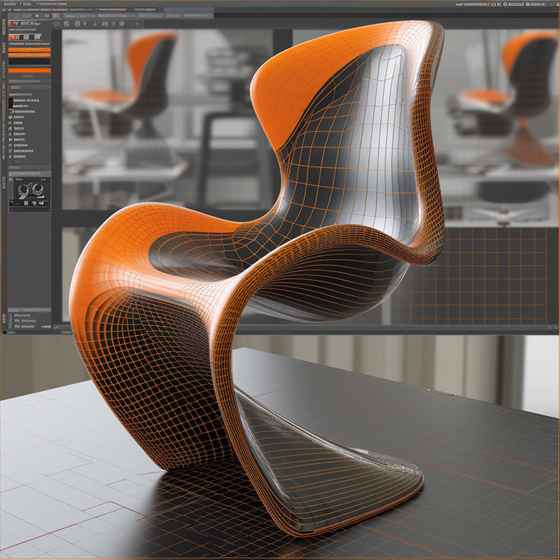
Design Intent
The central question in parametric CAD is not just "what does this look like?" It is "what should stay true when something changes?" A well-built model captures the designer's assumptions in sketches, dimensions, equations, references, planes, feature order, and assembly mates. When the overall length changes, mounting holes may remain symmetric. When material thickness changes, bend radii and relief cuts may update. When a product family gains a larger size, dependent parts may stretch without breaking.
This is why parametric modeling rewards careful thinking early. A quick model can be faster to create, but a thoughtful one is faster to revise, reuse, document, simulate, and manufacture. In engineering organizations, that difference compounds across product variants, supplier changes, tooling updates, and years of maintenance.
Sketches, Constraints, and Features
Most parametric models begin with constrained sketches. Lines, arcs, circles, and splines are tied together with dimensions and geometric rules such as parallel, concentric, tangent, coincident, equal, horizontal, vertical, and symmetric. The sketch then drives features such as extrudes, revolves, sweeps, lofts, holes, fillets, chamfers, shells, ribs, drafts, patterns, and sheet-metal bends.
The feature history matters. A fillet placed too early can break when a later cut changes an edge. A sketch that references unstable geometry can fail when a parent feature is edited. Skilled modelers build stable reference geometry, name important parameters, avoid unnecessary dependencies, and make the feature tree readable enough that another designer can understand it later.

Parameters and Equations
Parameters turn repeated decisions into controlled variables. A furniture designer might define seat_width, back_angle, rail_thickness, and fastener_offset. A machine designer might define shaft_diameter, bearing_clearance, plate_thickness, hole_pitch, and motor_mount_pattern. Equations and conditional rules can connect those values so the design behaves predictably as sizes change.
This is especially useful for configured products. A single master model can drive several sizes of a bracket, family of enclosures, series of valves, line of cabinets, or set of fixtures. The same approach supports quoting, automated drawings, downstream bills of materials, and manufacturing data when the CAD model is connected to product data management or enterprise systems.
Assemblies and Product Families
Parametric modeling becomes more powerful, and more delicate, at the assembly level. Parts can be positioned with mates, constraints, references, skeleton sketches, layout parts, or master models. A change to one part can update nearby components, motion envelopes, fastener placement, clearance zones, and drawings.
Assemblies should be structured so they can survive normal engineering change. That means avoiding circular references, separating layout intent from production geometry, keeping purchased components stable, and deciding whether a dimension belongs in a part, a shared parameter table, or a top-level assembly. The goal is controlled propagation, not surprise propagation.
Simulation and Analysis
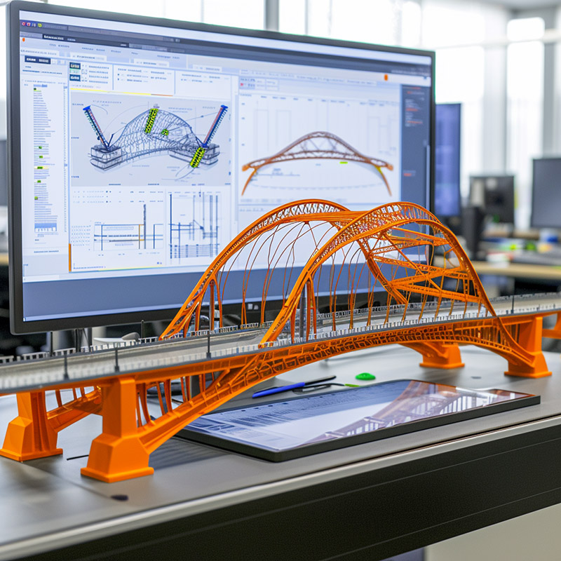
Parametric models are natural partners for simulation. Because the model is editable, engineers can vary wall thickness, rib placement, lattice density, bracket shape, hole location, or material choice and compare the effect on stress, deflection, mass, heat transfer, fluid flow, vibration, manufacturability, and cost. In better workflows, simulation is not a late-stage gate; it becomes part of design iteration.
The catch is that simulation needs clean, appropriate geometry. A detailed production model may contain tiny fillets, cosmetic features, embossed text, or hardware that make meshing harder without improving the answer. Engineers often simplify or derive analysis models, preserving the parameters that matter while removing features that do not affect the result.
Architecture and Computational Design
In architecture, parametric modeling is often connected to computational design. Designers use rules, scripts, and data inputs to explore forms that respond to daylight, structure, facade repetition, circulation, energy goals, code limits, or fabrication methods. Tools such as visual programming, building information modeling, and environmental analysis make it possible to evaluate many alternatives before choosing a buildable scheme.
The strongest architectural parametric work is disciplined, not merely complex. A facade pattern, roof shell, bridge, or urban plan should connect formal variation to performance, assembly, cost, maintenance, and construction logic. Otherwise the model becomes an attractive object that is difficult to document and build.
Customization and Additive Manufacturing
Parametric modeling fits customized products because it can preserve a design while changing its measurements. Orthotics, prosthetics, dental guides, eyewear, jewelry, bicycle components, furniture, packaging, tooling, and fixtures can be adapted around body scans, customer preferences, material choices, or machine limits. Additive manufacturing expands that opportunity, but it also makes constraint discipline more important because geometry must still meet strength, tolerance, support, surface-finish, and inspection requirements.
Cloud CAD and Collaboration
Parametric CAD used to be dominated by local files, manual copies, and careful check-in/check-out procedures. Cloud-native CAD and integrated product data management have changed how teams review, branch, merge, compare, and recover design work. Version history, permissions, comments, supplier access, and live collaboration are now part of the modeling environment for many teams.
This matters because parametric models are not just geometry. They contain decisions. A useful collaboration system makes it easier to see who changed a parameter, why a feature was added, which branch contains a test idea, and what will happen before a change is merged into the official design.
Model-Based Definition and the Digital Thread
Modern CAD increasingly treats the 3D model as the master product definition. Model-based definition adds dimensions, geometric tolerances, notes, product manufacturing information, materials, finishes, and inspection requirements to the 3D model itself. That can reduce the mismatch between drawings and geometry, support automated inspection, and help manufacturing, quality, service, and suppliers work from a consistent source.
Data exchange still matters. STEP, formally ISO 10303, remains a foundational standard for exchanging product model data between CAD, CAE, CAM, product lifecycle, and supply-chain systems. Parametric design intent is harder to move between tools than plain boundary geometry, so companies still need careful translation, validation, and documentation when models cross software boundaries.

AI, Generative Design, and Human Judgment
AI-assisted CAD and generative design are making parametric workflows more exploratory. Software can suggest geometry, create variations, search a design space, identify constraint problems, or help automate repetitive modeling steps. That does not remove the need for designers and engineers. It raises the value of clear constraints, validated requirements, manufacturable rules, and reviewable model history.
A generated shape is not a finished product definition. It still needs engineering checks, tolerances, material selection, assembly logic, manufacturing planning, inspection strategy, documentation, and lifecycle support. Parametric models provide a bridge between exploration and controlled production because they can turn a promising form into an editable, governed design.
Common Failure Modes
Parametric modeling fails when constraints are vague, excessive, hidden, or attached to unstable references. Symptoms include broken sketches, lost mates, failed rebuilds, drawings that do not update, configurations that work in one size but fail in another, or models that only the original designer can safely edit. These problems are usually workflow problems, not software problems.
Good habits help: fully define important sketches, use named parameters, model around datums rather than incidental edges, keep feature trees organized, test the extremes of configurations, document design assumptions, and simplify models before sharing them with suppliers who only need manufacturing geometry.
Alibre, Algor, and Early CAD-to-Analysis Links
Algor's 2002 support for the Alibre Design 3-D parametric modeling package was an early example of a larger shift toward connected CAD and analysis workflows. Engineers could use the Alibre Design Import Extender to open native Alibre Design parts and assemblies in Algor for analysis, including stress, heat transfer, fluid flow, electrostatic, MEMS, mechanical event simulation, and multiphysics work.
At the time, the promise was direct geometry transfer from a lower-cost 3D design package into finite element analysis. That same goal remains familiar today, although the surrounding environment has changed. Modern workflows now emphasize cleaner model preparation, simulation-driven design, cloud collaboration, product data management, model-based definition, and neutral standards such as STEP for exchanging product information across tools and supply chains.
Why Parametric Modeling Still Matters
Direct modeling, subdivision modeling, mesh modeling, and sculptural tools all have important roles, especially for concept work, industrial design, reverse engineering, and organic shapes. Parametric modeling remains essential when the design must be precise, revisable, configurable, documented, simulated, manufactured, inspected, and maintained. It is less about making a pretty 3D object and more about making a product definition that can survive change.