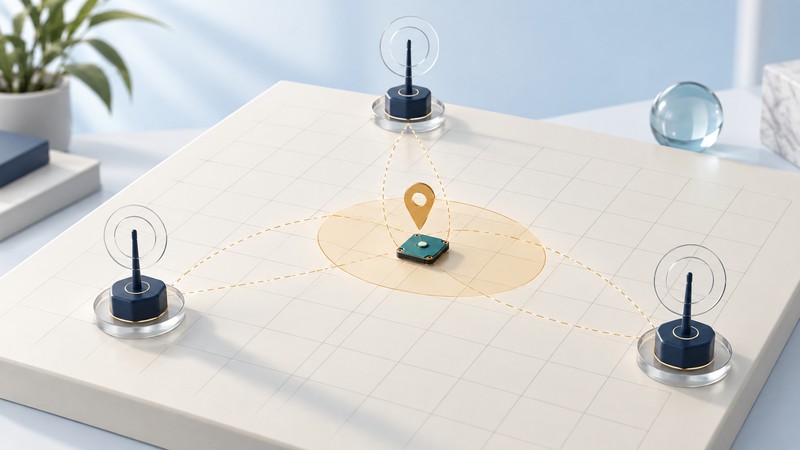
A wireless location engine estimates a position from measurements and known reference points. The historical Texas Instruments CC2431 provides a concrete example: it combines an IEEE 802.15.4 radio and processor with hardware that uses signal-strength information for a position estimate.
This explanation is for readers comparing location claims or studying an older design. The CC2431 is a historical engineering case, and its specific location engine should not be assumed to exist in every Zigbee device.
Follow the inputs to the estimate
The TI CC2431 product documentation describes an integrated location engine and Zigbee stack support. Fixed reference nodes supply known coordinates; a node whose position is unknown collects received signal strength indicator (RSSI) information related to those references. The engine uses those inputs to estimate coordinates.
The CC2431 datasheet, location-engine section specifies three to sixteen reference nodes, a 64 by 64 meter location range and 0.25 meter readout resolution. It lists calculation time from 50 microseconds to 13 milliseconds. These are distinct parameters: the coordinate step is a representation limit, and the calculation time describes computation. Neither supplies a field accuracy guarantee.
On a narrow screen, scroll sideways. Keyboard: focus the table and use the arrow keys.
| Claim | Meaning | Evidence still needed |
|---|---|---|
| Readout resolution, meters | Smallest coordinate increment represented | Error against surveyed or otherwise measured truth |
| Calculation time, seconds | Time spent estimating from supplied inputs | Measurement, communication and reporting delays |
| Position error, meters | Distance between estimate and reference truth | Test locations, conditions, sample count and distribution |
| Update interval, seconds | Time between delivered estimates | Missing updates and age of the latest valid result |
| Zone accuracy, percent | Share of samples assigned to the correct defined zone | Boundary cases and a stated denominator |
Calibrate the model and test the layout
RSSI is influenced by distance, obstructions, reflections, antenna behavior and the environment. A calibration measured in an open space may produce different results among shelves or moving people. Reference coordinates must use the same origin, axes and units as the output.
TI's CC2431 development-kit guide describes averaging RSSI information from responding reference nodes and performing estimation at the unknown-position node. Its setup procedures illustrate the need to configure references and parameters consistently. Use those device-specific procedures when reproducing that historical platform.
For a new evaluation, mark measured test points across the useful area, including edges, corners and important zone boundaries. Keep some points separate from calibration. Test at different tag orientations and representative occupied conditions. Recheck after moving references or materially changing the environment.
Calculate a position error you can interpret
Fictional two-dimensional example: a tag's measured true position is (4, 3) meters and its reported position is (7, 7) meters, using the same origin and axes. The horizontal differences are 3 and 4 meters. The position error is √(3² + 4²) = 5 meters.
This one result says nothing about the average or worst case elsewhere. Repeat at the planned test points and retain each true position, estimated position, timestamp and validity flag. Include missing results in availability reporting.
For a zone-tracking task, calculate the share of valid estimates placed in the correct zone and report how often estimates are missing. For coordinate tracking, report a distribution of errors rather than only the best point. Define your percentile method, sample count and sampling interval so another evaluator can reproduce the calculation.
A stale position can look precise on a map. Record the measurement time and delivered-result time, and define when the application should label a result stale. That threshold belongs to the task's requirements.
Ask what the location system actually proves
Before accepting an accuracy claim, request the reference layout, calibration method, antenna and tag orientation, tested environment, measured ground truth and error distribution. Ask whether the result describes a stationary tag, moving asset or room classification.
For a historical chip reproduction, confirm component and tool availability through TI's current product resources. For a new system, compare current supported platforms against the same task and measurement plan. The durable lesson is the evaluation method: known inputs, representative conditions, independent test points and a clearly defined useful result.
See Zigbee network roles and compatibility, asset-location pilot planning, and RTLS interoperability checks for adjacent decisions.