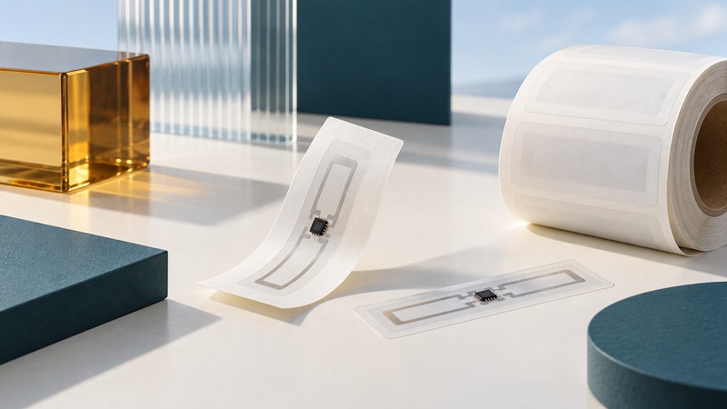
A thin RFID tag is a package of radio components and materials. Its usefulness depends on whether that complete package fits the surface, carries the required identity, survives handling and remains readable in the intended workflow.
Begin with the physical item and its lifecycle. Record the available label area, surface material, attachment method, expected handling, reader system and data requirements. Thinness is one constraint among these, and a bare inlay dimension is different from a finished label dimension.
Specify the construction you are buying
An inlay contains a chip and antenna on a supporting substrate. A dry inlay is supplied for incorporation into another construction. A wet inlay includes adhesive and a release liner. A converted label adds the printable and protective layers required by its application. Supplier terminology and available variants should be checked in the exact specification.
Avery Dennison’s RFID converting overview describes the integration of inlays into labels and tags. Ask the converter to identify all relevant layers, finished dimensions and thickness. The construction that leaves a label press may differ substantially from the inlay pictured in a chip brochure.
On a small screen, scroll sideways to read both columns.
| Field | Why it matters |
|---|---|
| Radio and chip | Supported protocol, regional application and memory for the agreed encoding. |
| Antenna and finished size | The antenna must fit intact; the finished label also needs space for adhesive, printing and placement tolerances. |
| Surface and adhesive | Compatibility with the material, curvature, application conditions and intended removal or permanence. |
| Mechanical and environmental limits | Specified bend, temperature, moisture, cleaning and abrasion conditions, with test evidence. |
| Supply and verification | Exact model/variant, converter lot, customer approvals and applied-product test results. |
Read dimensions and memory literally
A product specification can list antenna dimensions separately from die-cut dimensions. For example, the AD Longbow U9 page lists a 70 × 8 mm antenna and a 73 × 10 mm die cut, with dry, wet and label variants. These figures describe that product; they do not establish the size of another converter’s finished label.
Reserve room for manufacturing and placement tolerances. Keep the antenna intact when converting or applying the label. Ask where the chip lies relative to a fold, seam, roller or curved surface. A label that fits a flat drawing may be unsuitable once the package is formed.
Check EPC and user-memory capacities separately and confirm the supported encoding with the application team. More memory is useful only when the workflow can write, read and interpret it. Use the EPC encoding guide before selecting a chip based on a single capacity number.
Test the final surface and handling
The object and its surroundings affect the antenna. Metal, liquid contents, foil packaging, close stacking and orientation can change the response. Choose a construction designed for the intended material and test it after attachment. An ordinary thin label placed on a metal asset is a different case from a purpose-built on-metal tag.
For durability, request the test conditions and acceptance result behind the claim: material, temperature, exposure time, cleaning agent, number of cycles and read-check method. Avery Dennison’s AD Dura 2.0 description illustrates a reinforced construction offered for demanding environments. Its product-specific claims should be matched to the exact variant and application; “durable” alone is not a test condition.
Compare samples through the whole job
- Obtain documented samples of each candidate and label them with their exact part numbers and lots. Keep an unapplied reference sample.
- Apply them using the intended process and permitted conditions. Record placement, surface preparation and the final product configuration.
- Verify encoded identity and reader compatibility, then run the representative read task before handling.
- Expose samples to the expected packing, use and handling sequence within approved product instructions. Inspect adhesion and physical damage, then repeat the same read task.
- Compare failures, read performance and practical application effort. Select against defined requirements, document exceptions and preserve the accepted sample.
Keep reader configuration consistent while comparing constructions, or record each deliberate change. Separate unreadable tags from correctly read tags carrying incorrect data. The read-test guide helps keep those measurements reproducible.
Printer compatibility is another check: media pitch, inlay position, thickness and feed path must suit the actual printer and encoder. Refer to the RFID printing guide and manufacturer instructions. Revalidate when the converter changes an inlay, adhesive, facestock or manufacturing process that could affect the accepted result.
Take the guide into your workflow
Download the working checklist (plain text). The editable text file includes its purpose, instructions, evidence fields and a link back to this guide. Record observed results and unresolved questions before making the decision.
Related reading
- Understand apparel labels and care questions
- Connect label selection to customer acceptance
- Check the complete reader and tag combination
- Explore all RFID guides
Researched and updated September 11, 2026. Recheck the linked primary sources when equipment, standards or operating requirements change.