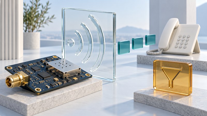
A cable-telephony tuner belongs to the radio-frequency receive path. It helps select and condition the signal arriving over coax before later circuitry recovers data and voice software handles calls. Following those layers explains why a small RF component could matter to a telephone service.
This is a technical retrospective and block-diagram reading exercise. It preserves the specialist meaning of “microtuner”: RF reception in a cable device. It is not a guide to adjusting a VoIP application's audio or modifying cable equipment.
Place the Microtune example in context
The MT2060 is a historical Microtune silicon tuner. The Linux kernel's media-driver documentation identifies it as a silicon intermediate-frequency tuner. That supports its component role; it does not establish current availability, cable-operator approval or the performance of a complete modem.
In a traditional tuner architecture, frequency selection and conversion place a received channel into a form the next processing stage can use. Filtering and gain behavior affect reception alongside the rest of the RF design. Integration can change board area, external components and power requirements, but a smaller package alone does not quantify whole-device savings.
Trace a conceptual downstream voice path
- Coax and RF receive front end. The receiver accepts the cable signal and performs the selection, conditioning and conversion required by its architecture.
- Demodulation and DOCSIS processing. Receive processing recovers the carried data; the cable-modem system handles the DOCSIS access connection.
- IP delivery and voice terminal functions. The voice client participates in call signaling and processes media for the service.
- Audio and telephone interface. Conversion and line-interface functions deliver audio to a supported analog telephone.
This ordered diagram follows downstream received speech. Outgoing speech uses the corresponding media processing and the modem's upstream transmission path. Call signaling and provisioning also cross the network. The blocks describe functions, which may share silicon; modern receiver designs need their own documented topology.
CableLabs' specifications directory separates DOCSIS access technology from PacketCable multimedia services. In the historical PacketCable 1.0 architecture report, section 6.1, the multimedia terminal adapter supplies the subscriber interface, codecs, call signaling and media encapsulation. Its embedded cable modem provides the access connection. The report explicitly presents functional roles rather than a mandatory product partition.
Swipe horizontally, or focus the table and use the arrow keys.
| Layer | Useful evidence | What remains to check |
|---|---|---|
| RF reception | Model-specific receiver or cable-channel status | Access registration and voice-service state |
| DOCSIS access | Modem registration and the operator's connection diagnostics | Voice provisioning, signaling and media |
| Voice client | Provider voice status and representative call evidence | Two-way audio and telephone-interface behavior |
| Telephone interface | Supported endpoint checks and observed ring/audio behavior | Whether the complete call works in both directions |
Use a fault to test the diagram
Fictional layer-identification exercise
A gateway reports an established cable connection and its internet service works, but incoming voice calls fail. Which component has been proven faulty? None from those facts alone. The next useful evidence is the voice-service state, call direction and timestamp, followed by the provider's investigation. The observations establish part of the access path; they leave voice provisioning and routing open.
A second case has both internet and voice unavailable. Begin with the provider's supported connection and outage checks, because the services share access dependencies. That symptom still cannot identify a particular tuner chip. Hardware diagnosis requires the exact design, appropriate instruments and qualified personnel.
When comparing historical component announcements, ask for the test conditions, external circuitry, receiving standard and boundary of a power figure. Keep chip-level claims distinct from board-level measurements and field reliability. Omit numerical conclusions when the original evidence cannot be authenticated.
Label the layers yourself
Download the RF-to-voice layer exercise, including answers and a blank evidence map. Continue with household cable-voice checks, analog SLIC and codec functions or SoC integration boundaries.