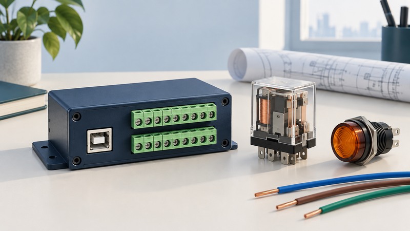
A USB digital I/O module lets a computer read electrical states or command outputs. “Relay output” can describe a built-in switch, an output intended to drive an external relay, or a controller for separate relay modules. Read the circuit and terminal description before choosing the device.
Begin with an ordinary low-voltage bench-control task and a written definition of the load’s inactive state. USB and desktop software are useful for supervision and testing; safety functions and precise timing require an architecture specifically designed and verified for those jobs.
Identify what the terminals actually provide
On a narrow screen, scroll the table horizontally. Keyboard users can focus the table region and use the arrow keys.
| Output | What it supplies | Selection questions |
|---|---|---|
| Logic-level digital output | A signal referenced to an output ground. | Voltage thresholds, source/sink limits and external driver needs. |
| Transistor or open-drain driver | A switching path with polarity and electrical limits. | Load supply, return connection, off leakage, voltage drop and transient protection. |
| Electromechanical relay | Moving contacts, often common/NO/NC. | Contact ratings for the actual load, minimum load, life, switching time and bounce. |
| Solid-state relay | An electronic switch with specified on/off behavior. | AC/DC compatibility, on resistance/drop, leakage, temperature and load limits. |
A USB connector usually powers the interface electronics; an output switch may still require an external load supply. The output and its wiring must meet the exact module’s specifications. A current rating does not establish acceptable inrush, inductive switching or combined-channel loading.
Digilent’s USB-ERB family information describes electromechanical relay devices with configurable startup behavior. That behavior illustrates why configuration belongs in the acceptance record instead of being inferred from a generic relay symbol.
Read the DT9817-R as a specific example
The DT9810/DT9817 Series manual, UM-21223-T (December 2025) identifies eight digital inputs and eight digital outputs on the DT9817-R. Table 29 describes its outputs as solid-state relays and its isolation as functional. The operating description says an output bit of 1 closes the switch and 0 opens it; an external voltage is needed for the switched output.
Use the DT9817-R sections, especially the connection example on printed page 40 and specifications on page 94. Adjacent models in the same manual have different outputs. Functional isolation is not a general approval for protective isolation or mains switching. Preserve the distinction between a component’s breakdown limit and its permitted operating conditions.
This guide uses that device to illustrate how to read a module manual. Confirm hardware revision, driver support and the application’s requirements before retaining or replacing an existing installation.
Write the load and state requirements
Record supply range, normal current, startup/inrush behavior, inductance, required switching frequency and the consequences of an unwanted transition. For a relay coil or solenoid, ask for the manufacturer’s specified suppression method. Stored magnetic energy can create a voltage transient when current is interrupted.
The USB-ERB08 manual’s contact-protection section shows why inductive loads need attention. Protection depends on AC/DC operation, driver topology and the load’s release-time requirement. Use the procedure for your actual equipment; a diode added indiscriminately is not a universal solution.
Test the states around the command
On a narrow screen, scroll the table horizontally. Keyboard users can focus the table region and use the arrow keys.
| Event | Required behavior to define | Evidence to record |
|---|---|---|
| Power applied before software starts | Indicator remains inactive until an explicit command. | Observed output during the complete startup interval. |
| Valid on/off command | Output changes as requested; feedback agrees. | Command, result, timestamp and measured load state. |
| Application closes or crashes | Defined inactive or retained state, selected for the task. | Physical output, not just the last screen value. |
| USB cable or hub power is lost | Predetermined behavior for that failure. | Output state and delay under each separate interruption. |
| Communication returns | Deliberate reinitialization before outputs are enabled. | Whether old commands are replayed or a fresh command is required. |
These are requirements to test, not promises made by every module. If the hardware cannot provide the required state independently of software, change the hardware or control architecture. Repeatedly writing “off” from a disconnected computer cannot control an output.
Readback may report an output register rather than the load itself. Where physical confirmation matters, use appropriate independent feedback. Check whether a command changes one line or rewrites an entire port so that unrelated outputs retain their intended state.
Make errors diagnosable
Start with the vendor’s example utility, then add your application. Identify the module by a stable serial or configured identity; USB enumeration order can change. Record driver and firmware versions with the mapping from channel names to terminals.
Handle timeouts, disconnected devices and invalid responses explicitly. Reopen and verify the intended device after recovery, initialize outputs, and require a deliberate enable where appropriate. A successful API call may only confirm that a request was accepted; verify the documented completion semantics.
For repeatable timing, determine whether the module offers hardware-timed operations and what their limits are. Measure end-to-end behavior in the real host/hub arrangement. Keep application logs and the physical-state test record together so a later failure can be traced to a layer.
Keep a working record
Download the usb relay and digital i/o modules worksheet (editable text). Save a copy for each comparison or test. It includes the example assumptions, fields for source references and space for your results.