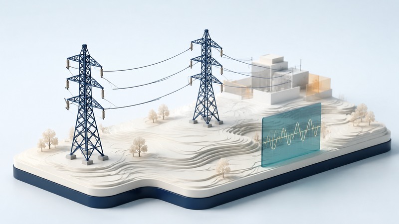
The transmission grid carries large amounts of electricity between generation and demand areas. Its useful capacity depends on the connected system: equipment heating limits, acceptable voltages and the ability to remain stable after disturbances. An upgrade proposal should identify which limit it addresses and demonstrate the result under stated conditions.
This is a guide to interpreting grid descriptions and planning evidence. Engineering studies and operating decisions require the responsible utility or system operator.
Follow the delivery chain
EIA’s electricity-delivery explanation describes the roles of transmission lines, substations, transformers and distribution networks. Transformers change voltage for different stages of delivery; high-voltage transmission supports long-distance transfer, while local distribution reaches individual customers.
Interconnection provides multiple possible paths and opportunities to share resources. In an AC network, power flows according to the electrical properties and operating state of the connected network. A commercial transaction does not reserve a single physical route from one generator to one buyer.
That is why a project must be assessed beyond its own right-of-way. Adding or removing a line, generator or large load can alter flows and voltages elsewhere. Identify the study region and relevant neighboring systems when reviewing a proposal.
Distinguish real and reactive power
Real power, measured in watts and commonly MW on the grid, supplies net energy for loads. Reactive power, measured in var and commonly Mvar, describes energy exchanged with electric and magnetic fields in AC equipment. Its management helps maintain acceptable voltage.
FERC’s technical explanation of reactive capability notes that resources may need to supply or absorb reactive power to maintain voltage while real power is delivered. The linked 2021 presentation is used here for that physical role, not as a statement of today’s compensation rules.
Generators, capacitors, reactors, synchronous condensers and appropriately controlled power electronics can provide different forms of support. Compare their response, operating range and location in the studied system. A synchronous condenser principally supplies or absorbs reactive power; its Mvar rating is a different quantity from a power plant’s MW output.
Identify the binding constraint
FERC’s Electric Reliability Primer explains thermal, voltage and stability limits. These are complementary checks: passing one does not establish that a transfer is acceptable under the others.
On a narrow screen, scroll the table sideways. Keyboard users can focus the table region and use the arrow keys.
| Constraint | What must remain acceptable | Evidence to request |
|---|---|---|
| Thermal | Equipment heating and line clearance at the applied loading | Applicable ratings, weather assumptions and loading results. |
| Voltage | Voltage levels and recovery with available reactive support | Operating cases, reactive margins and disturbance results. |
| Stability | The system’s ability to maintain or regain coordinated operation | Disturbance models, protection assumptions and study findings. |
Ask whether the result covers normal operation and credible equipment outages. The loss of one element can redistribute power to the remaining network and change reactive requirements. Reliability criteria determine which events and consequences the planner must evaluate.
Fictional simplified corridor: two parallel paths each carry 80 MW and each has a stated applicable thermal limit of 100 MW. If one path trips and all 160 MW must transfer over the other, its 100 MW limit is exceeded. Normal-operation headroom therefore did not establish outage-case capability.
Real networks have more paths, controls and possible redispatch. This illustration only demonstrates why a normal loading figure needs a contingency study; it does not calculate a real corridor’s secure transfer limit.
Evaluate what an upgrade actually changes
A new line or transformer can address some transfer constraints. Reactive-support equipment addresses voltage needs. Operating changes, local generation, storage or dependable demand flexibility may change the flows at critical times. Ask the planner to compare feasible alternatives against the same identified need.
Request the study date, demand and generation assumptions, applicable ratings, tested outages, model versions and proposed in-service date. Separate a planning recommendation from permits, construction and demonstrated operation. For cost comparisons, retain land, interconnection, maintenance and other included scope.
When a claim says an upgrade “prevents blackouts,” ask which failure modes were evaluated and what residual risks remain. The outage-cause guide explains how different faults and system conditions can produce interrupted service.
Use the demand guide to inspect the load assumptions and the green-power guide to distinguish electricity purchasing from physical delivery. A useful grid explanation connects the equipment to the specific problem it can solve.