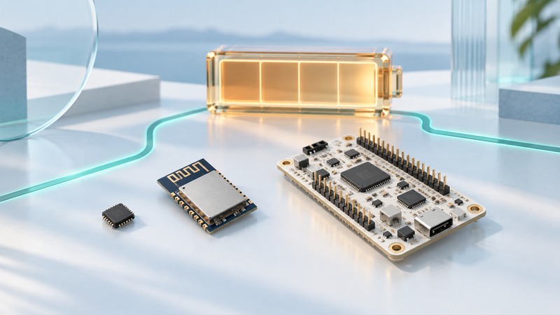
A small Wi-Fi device needs room and energy for a complete connection: antenna, radio, processor, power supply, software and application traffic. Choose hardware around that operating cycle. The smallest package or lowest sleep-current figure describes only one part of the product.
This guide is for embedded developers planning a connected sensor or compact appliance. Start with the payload, reporting interval, acceptable delay, power source, enclosure and supported Wi-Fi network. Use the exact component and board documentation for electrical design; the examples below are planning arithmetic.
Choose the integration level you can support
On a narrow screen, scroll the table sideways. Keyboard: focus the table and use the arrow keys.
| Starting point | What it provides | Work that remains |
|---|---|---|
| Wireless chip or SoC | Silicon radio and processing functions | RF design, supporting components, layout, software and product validation |
| Wireless module | A packaged radio implementation, sometimes including antenna and approvals | Host integration, power, antenna clearance and compliance with module conditions |
| Development board | Module or chip plus convenient power and programming interfaces | Product enclosure, production design and accounting for board overhead |
Early single-chip Wi-Fi products helped make wireless networking practical in small consumer devices. Today the useful comparison is the total implementation, including the engineering effort needed to support it. A development board can establish the application behavior before a smaller production layout is designed.
For a concrete design reference, Espressif's ESP32-C3 hardware guidelines organize the work into schematic and PCB checks. Its module-layout guidance shows why antenna placement and clearance are part of the footprint. Follow the drawing for the exact module; a convenient gap in an enclosure is not a substitute for its required layout.
Budget the connection cycle
List the states your application actually uses: boot or wake, network association, authentication, address acquisition, secure application connection, transfer, confirmation and sleep. A device that wakes frequently can spend appreciable time establishing a connection before it sends its small payload.
Espressif's ESP32-C3 Wi-Fi low-power guide distinguishes modes that maintain a connection from deep-sleep scenarios that require reconnecting after wake. Choose a supported mode according to response time and traffic, then measure the actual application. Keep the SDK version and configuration with the result.
Fictional equal-voltage example: suppose a device draws 120 mA for three seconds while connecting and sending, then 0.05 mA for the other 297 seconds of a five-minute cycle. Its average for those states is:
(120 × 3 + 0.05 × 297) / 300 = 1.2495 mA, about 1.25 mA.
If a poor connection extends the active period to fifteen seconds, the corresponding average is (120 × 15 + 0.05 × 285) / 300 = 6.0475 mA, about 6.05 mA. The changed connection time has a large effect even though the sleep setting is identical.
These invented inputs exclude other loads and do not predict battery life. Where currents are measured on different voltage rails, convert to power or energy at a common boundary and include conversion losses. Estimate usable battery capacity under the actual temperature, load and cutoff conditions separately.
Measure the whole assembled device
Measure at a defined power input using equipment that can capture both short peaks and the complete cycle. A slow display may hide brief transmit demand. Follow the hardware guide for measurement setup and supply capability, and observe whether voltage remains within the specified operating range during peaks.
Include the regulator, indicator LEDs, sensors, storage, display and host processor where fitted. Compare the development board with the production assembly only after accounting for these differences. Use the device energy worksheet to record states, units and the measurement boundary.
Test in the intended enclosure with its battery, cables and nearby materials. Record time to application confirmation, delivered payloads, retries and recovery after an ordinary loss of connectivity. A tiny board that performs well in the open can behave differently once installed.
Make recovery part of the design
Define how long the device tries before returning to a documented retry schedule. Keep pending data and configuration across supported restarts, and verify what the server receives after recovery. Test a wrong credential, unavailable access point, unavailable application endpoint and return to service in an authorized setup.
For a product with several wireless functions, use the combo-chip coexistence guide to test concurrent workloads. Retain exact order codes, firmware, antenna and enclosure details, power traces and acceptance results. Recheck those results when the board, SDK or connection policy changes.