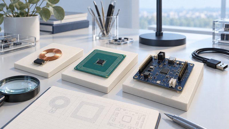
Texas Instruments RFID products span different frequencies and device roles. Begin with the full part number on the bill of materials or equipment documentation, then identify whether it is a reader transceiver, a transponder interface or a programmable sensor transponder.
A shared manufacturer name establishes neither radio compatibility nor application compatibility. Build the comparison from the actual datasheets, firmware requirements and assembled hardware.
Compare three documented device roles
On a small screen, scroll sideways to read all columns.
| Device and official documentation | Role and radio scope | What still needs checking |
|---|---|---|
| TRF7970A | 13.56 MHz NFC/RFID transceiver supporting protocols including ISO/IEC 14443 A/B and ISO/IEC 15693. | Host firmware, selected protocol, antenna circuit and required commands. |
| RF430FRL152H | 13.56 MHz ISO/IEC 15693 sensor transponder with a programmable MSP430 core. | Application memory map, sensor configuration, power arrangement and data interpretation. |
| TMS37157 | 134.2 kHz low-frequency transponder interface using the TI protocol. | Compatible LF reader, transaction timing, EEPROM use and host interface. |
These are semiconductor examples, not a list of complete interchangeable reader products. Their official pages link datasheets, application material and lifecycle information. Check the exact orderable suffix, package, errata, revision and support status before specifying or replacing a part.
The 134.2 kHz LF example operates in a different band from the two 13.56 MHz HF examples. A multi-protocol HF reader still needs support for the required HF command sequence and application data. A phone’s ability to read one NFC tag is similarly a test of that particular combination.
Verify compatibility through the complete stack
- Identify the part and its role. Record the package/orderable variant and source of the identification.
- Match the frequency, protocol and required operating mode between the assembled reader and transponder.
- List the actual commands and memory operations the application needs.
- Check host interface, logic levels, power, antenna matching and documented reference-design constraints.
- Verify the software’s interpretation of returned bytes and error states.
- Test the complete assembly with representative tags and mounting conditions.
The TRF7970A product documentation describes an analog front end and protocol framing with SPI or parallel host communication. That still leaves work for the host software and board design. Use the linked design guidance and errata for the selected implementation; avoid extrapolating a chip feature into a guaranteed finished-system read range.
Keep read and write tests separate. A successful identity read does not establish that application memory can be written under the same conditions, that locked fields can be changed, or that the application understands a sensor result.
Trace an apparent read success to a usable result
Keep the test bounded to the assembly and firmware actually used. Save a known response and its expected interpretation with the software test. If the hardware, antenna or application firmware changes, repeat the affected measurements. This guide supplies a review method, not a tested circuit or downloadable device driver.
Separate identification from authorization
A readable unique identifier helps distinguish a tag. Access decisions also depend on the credential application, authentication scheme, key handling, reader connection and permissions in the system. Request documentation of those functions for the exact credential and reader implementation.
Describe the evidence precisely: “read the identifier,” “read a protected application field,” and “completed an authenticated exchange” are different results. Do not infer cryptographic protection from an ISO radio-protocol number or from an identifier described as unique. For access-control designs, involve the owner of the credential system before changing chips, firmware or card types.
Keep a component evidence packet
Save the part number, dated datasheet revision, errata review, reference-design differences, firmware version and complete test configuration. Retain supplier traceability and a small set of known-good samples. Link every requirement to the document or test that supports it.
When maintaining older TI-based equipment, identify the complete product supplier as well as the chip. A currently listed chip does not establish that an old reader, driver or development board remains supported. Obtain a documented replacement path and repeat the application checks before treating a substitute as equivalent.
Keep a working record
Download the editable texas instruments rfid working record (plain text). Save a copy for each evaluation. It includes instructions, evidence fields and source links; record unresolved questions with their owner before signing off.
Related reading
- Choose a complete RFID reader
- Interpret tag-chip specifications
- Assess evidence behind security claims
- All RFID guides
Researched and updated October 3, 2026. Recheck the relevant source documents when equipment, software or requirements change.