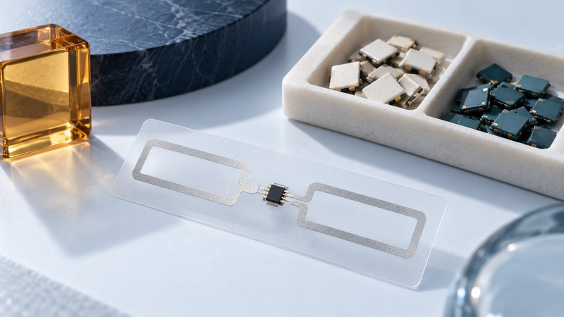
An RFID integrated circuit determines which radio commands, memory functions and security features a tag can support. The finished tag adds an antenna and physical construction that strongly influence how those capabilities work on a real item. Compare both levels before choosing a part or label.
This guide focuses on passive UHF tag ICs for technically involved buyers and designers. Start with the required identifier, any additional on-tag data, the intended read and write operations, and the reader software. Use the exact part revision and data sheet for an implementation.
Budget memory by its purpose
On a small screen, scroll sideways to read all columns.
| Area | What to establish |
|---|---|
| EPC | Available capacity for the selected identifier encoding and any supported configuration choices. |
| TID | Manufacturer/chip identification and whether this exact part provides the serial information the application expects. |
| User memory | Available size, supported access and the defined format of any application data. |
| Reserved/control functions | Supported password, access and lock behavior; which operations can be permanent. |
The EPC encoding guide explains the relationship between an item identity and its stored representation. Keep a written memory map that names each field, its length, encoding and owner. A capacity stated in bits needs to be converted carefully before allocating bytes: eight bits form one byte.
Count usable application space rather than adding every memory-bank headline together. Some configurations trade EPC and user space, and a field may have fixed layout or restricted access. Check the exact part's documentation and the reader commands that will write it.
Compare actual parts against one requirement
The NXP UCODE portfolio table, checked September 20, 2026, lists useful examples of distinct memory choices. Its figures below describe chip options, not guaranteed label read ranges.
On a small screen, scroll sideways to read all columns.
| Part | EPC memory | User memory | Listed read sensitivity |
|---|---|---|---|
| UCODE 9 | 96 bits | 0 bits | −24 dBm |
| UCODE 8 | 128 bits | 0 bits | −23 dBm |
| UCODE 8m | 96 bits | 32 bits | −23 dBm |
Read sensitivity and write sensitivity answer different questions
Sensitivity describes the input level needed for a specified operation under stated conditions. In comparable dBm specifications, a more negative threshold represents a lower required power level. A part's ability to respond to an inventory query and its ability to complete a write should be checked separately.
NXP's UCODE 7xm product page, for example, lists different read and write sensitivity values. Use that distinction when designing an encode station: success at a distant inventory read gives incomplete evidence for reliable programming at that location.
Compare measurement conditions, frequency, input configuration and test method before ranking parts. Then request the finished inlay's performance and test it on the actual product. An antenna, surrounding metal or liquid, orientation and available field can dominate the installed result. Retain failed writes and verify data after programming.
Select security functions by the action required
A fixed identifier, a password-controlled write and cryptographic authentication serve different purposes. State whether the application needs to prevent accidental edits, control access to data or verify a supported cryptographic response. Then check the exact IC feature and the corresponding reader and application support.
The NXP portfolio separates memory-focused parts from products with cryptographic functions. A label specified only by memory capacity leaves authentication requirements unresolved. Key provisioning and verification services also need an operating owner; hardware support alone does not deliver a managed authentication system.
Treat permanent lock operations as a controlled production step. First use test tags to verify the memory map and supported lock behavior. Confirm the intended tag selection and preserve a record of the result. Follow the device documentation for commands; copying a lock sequence from another part can make a useful tag unrecoverable.
Validate the converted tag and the lifecycle
Keep one comparison record containing part/revision, antenna/inlay, label conversion, attachment surface, reader configuration and required operations. Run reads, writes and any security operation at representative positions and after the handling conditions relevant to the product.
Choose a part through its demonstrated fit to that record. Revisit the decision when the IC revision, inlay construction, converter, encoding software or product surface changes. The thin-tag guide covers materials and mechanical choices; the printing guide covers controlled encoding and rejected labels.
Keep a working record
Download the editable working record (plain text). It includes purpose, instructions, evidence fields and this guide's source links. Save a separate copy for each evaluation and record unresolved issues with their owner.
Related reading
- Understand identifier encoding
- Choose finished tag construction
- Encode and verify labels
- All RFID guides
Researched and updated September 20, 2026. Recheck source documents when equipment, software or applicable requirements change.