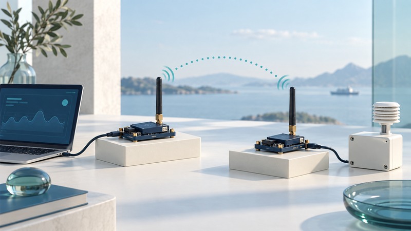
An RF modem carries data between a host interface and a radio link. Select it by the complete telemetry path: electrical interface, serial format, radio protocol, allowed installation, delivery behavior and application timing. A matching frequency or connector alone cannot establish that two devices will exchange usable records.
This guide helps technicians and embedded-system designers plan a documented test. Use the exact module and carrier-board manuals, approved power and antenna arrangements, and a noncritical bench setup. Electrical connection and radio authorization depend on the actual hardware and jurisdiction.
Match the interfaces before the radios
On a narrow screen, scroll the table sideways. Keyboard: focus the table and use the arrow keys.
| Requirement | What to confirm | Consequence of a mismatch |
|---|---|---|
| Host electrical interface | TTL-level UART, RS-232 or RS-485; voltage limits and required transceiver | An unsuitable connection may fail or damage equipment |
| Serial format | Baud rate, data bits, parity, stop bits and flow control | Corrupted records or overflowing buffers |
| Radio interoperability | Exact product family, protocol, firmware, network settings and security configuration | Radios can share a band without understanding each other |
| Installation | Region-approved variant, antenna, enclosure and power requirements | Bench results may not transfer to the intended installation |
| Application behavior | Message framing, timeout, acknowledgment and duplicate handling | A delivered radio packet may still leave an incomplete application transaction |
Keep interface conversion explicit. A USB development board can supply host adaptation that the bare module lacks. Use a documented evaluation kit when establishing a first baseline, and treat integration into the final enclosure as a separate validation step.
Choose transparent or framed operation
Transparent operation presents received data through the serial interface with relatively little host involvement. Framed API operation supplies structured messages that can include addressing, status and other information. Digi's API-mode explanation describes that distinction for supported XBee radios and the availability of transmission status information.
For a bounded example, use two compatible XBee-PRO 900HP modules on their supported development boards, configured according to the 900HP mode comparison. Confirm the regional variant, firmware and documented matching network settings before powering the test. The module family's name does not replace those checks.
Start with a known configuration and a short numbered test message. For transparent mode, verify the bytes at the receiving serial terminal. For API mode, use the matching frame documentation or vendor tool and inspect the relevant transmit status and receive frame. Preserve addresses and configuration exports with the test results.
Budget bytes and time
Fictional serial budget: an application sends a 100-byte record five times per second. That is 500 bytes per second. With asynchronous 8N1 serial framing, each byte uses ten line bits, so the application consumes 5,000 bits per second before any extra host-side framing. On a 9,600-bit/s serial link, that is about 52.1% of nominal line capacity.
Radio headers, acknowledgments, retries, packetization delay and competing transmitters add separate demands. Leave room for bursts and responses; increasing the UART rate does not automatically increase the usable radio payload rate. Verify buffer sizes, flow-control behavior and timeout settings in the exact firmware manual.
For a polling protocol, measure request-to-response time at the application. A radio acknowledgment establishes a radio delivery event with its documented scope. The receiving application may still reject a checksum, address or command. If using Modbus or another timing-sensitive protocol, validate its actual transaction sequence over the radio arrangement.
Test delivery and recovery
The serial telemetry test record separates transmitted records, unique valid received records, duplicates, gaps and application confirmations. Number the test records so a duplicate cannot be counted as a new success.
Run an initial bench test, then repeat at the intended site using approved equipment and representative enclosure placement. Record the payload, interval, distance, obstructions, antenna arrangement, firmware and other active equipment. Evaluate each direction when both are used. Report the tested conditions alongside the result instead of claiming a universal range.
Fictional result: send 100 numbered records and receive 97 unique valid records plus two duplicate arrivals. Unique delivery is 97/100 = 97%; duplicates do not increase that percentage. The missing three records require explanation against the application's acceptance criteria.
In an approved test setup, use the vendor-supported restart procedure and observe reconnect time, queued records and configuration persistence. Confirm the application's final state. Preserve a known working baseline before changing retry or packetization settings, then repeat the same workload after each change.
For broader service diagnosis, use wireless infrastructure fault isolation. For end-to-end offline records, use wireless systems reliability. Both help keep successful radio transport connected to the outcome the system actually needs.