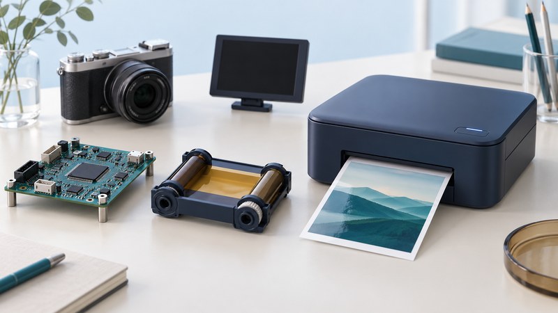
A photo-printer development platform brings together the controller board, embedded software, development tools and interface to the print engine. TAK Imaging’s SKRRPP-DS, described in September 2005, is a useful historical example: its purpose was to prototype dye-sublimation photo printers. The engineering question is how reliably the whole system turns an input image into the requested physical print.
What the 2005 platform brought together
TAK’s September 2005 announcement described an S1 system-on-chip board, up to 128 MB of DRAM, memory-card connections, USB host and device connections, debug access and display interfaces. Its software package covered image processing and input paths from computers, cards and PictBridge cameras, with compilers and debugging tools for the embedded processors.
Read that description as a historical platform specification. A present-day engineering project would need the actual board revision, licensed toolchain, firmware source or documented interfaces, schematics and supported engine list before relying on it. Current availability and support for this legacy kit have not been established.
The announced 2.4-second image-processing figure for a four-megapixel image is a dated TAK performance claim. The available announcement gives too little benchmark detail to reproduce it independently. It leaves input encoding, processing settings and complete paper-handling time to be established in a system test.
Trace the job through the system
On narrow screens, focus the table and use the arrow keys or swipe to see every column.
| Stage | Evidence to capture | Useful failure test |
|---|---|---|
| Receive and decode | Exact image, format, dimensions and successful decode | Truncated file or unsupported format produces a clear error. |
| Transform and buffer | Crop, orientation, color settings and peak memory use | A large supported image completes without corrupting another job. |
| Schedule and drive the engine | Engine revision, command sequence and job state | Paper or ribbon exhaustion leaves an accurate recoverable state. |
| Deliver and report | Finished sheet, completion time and final status | Cancellation or disconnection is handled at a documented boundary. |
The image-processing program and the engine controller have different jobs. One prepares image data; the other coordinates the physical printing mechanism and reports its state. A prototype demonstrates integration only when both sides agree on dimensions, data format, timing and job status.
Canon’s 2003 PictBridge direct-print guide shows how camera settings control paper size, layout and image options, with some choices depending on the camera. This illustrates why a USB connector alone leaves application behavior unresolved. For a camera-to-printer test, record both devices, their software versions and the options actually negotiated.
Measure first-print latency and sustained output
Define start and stop events before testing: for example, accepted print request to fully ejected sheet. Also record time to first sheet and the interval between later sheets in a multi-image job. A system can prepare one image while another prints; when stages overlap, use an event timeline instead of adding their durations blindly.
Repeat the same file set with the same quality mode, crop and consumables. Report a range and the number of runs. Include a high-detail image, a portrait, a rotated image and a maximum supported size so that a single convenient file does not stand in for the workload.
Turn a demonstration into an acceptance record
- Freeze the configuration. List board, engine, firmware, compiler, memory and input-device versions. Save the test images and expected settings.
- Check the actual sheet. Inspect orientation, crop, margins and visible defects under consistent viewing conditions. Keep the output with the job log.
- Exercise recovery. Use the engine maker’s supported procedures for cancellation and consumable faults. Confirm the next valid job completes correctly.
- Record resource limits. Measure memory and timing at the supported maximum workload, including queued jobs where applicable.
- State the result narrowly. Name the tested combination and remaining untested features. A working board demonstration is one step toward a supported product.
For an existing printer, use its supported driver or protocol and exact manual. Embedded prototype work requires the engine documentation; connector appearance is insufficient to infer electrical compatibility.