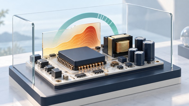
An integrated offline power switch combines a high-voltage switching device with control functions used in an AC-powered converter. Integration can simplify the component arrangement, while the complete supply still depends on its magnetics, capacitors, feedback, protection, layout and thermal design.
Compare devices by the service required from the finished supply: input range, output power, enclosure, ambient temperature, standby behavior and fault response. This guide is a datasheet-reading aid for electronics readers and engineering reviews.
Understand the controller and switch roles
The power transistor controls energy transfer through the converter's magnetic components. The controller determines when switching occurs in response to regulation and protection signals. Control methods differ: a conventional PWM device and a device using on/off cycle control should be assessed under their own documentation.
Power Integrations' TinySwitch-4 family datasheet, revision G, October 2020 provides a concrete example of an integrated MOSFET and on/off controller. It is used here to demonstrate how conditions alter a rating, not as a product recommendation.
At block level, trace input conversion and filtering, the integrated switch and transformer, output rectification/filtering, and the feedback path. An isolated design also needs a defined insulation barrier. Follow the actual topology when deciding which losses and protection functions belong to the chip and which belong elsewhere.
Read every power figure with its footnotes
On a narrow screen, scroll the table sideways. Keyboard users can focus the table region and use the arrow keys.
| Item | Record with the value | Reason |
|---|---|---|
| Voltage limits | Operating conditions, absolute limits and transient assumptions | A semiconductor blocking rating differs from the permitted AC input |
| Power capability | Input range, package, enclosure and ambient conditions | The same device can support different power under different thermal conditions |
| Current limit | Tolerance, mode and temperature dependence | Transformer and fault behavior depend on more than nominal current |
| Thermal behavior | Loss estimate, thermal path and shutdown/recovery definition | Normal operation needs margin before protection intervenes |
| Protection | Trigger, delay, response and reset requirements | Restarting and latched shutdown serve different system needs |
For example, the cited datasheet lists TNY285P/D at 6 W for a typical enclosed adapter across 85–265 VAC and 11.5 W for peak/open-frame service in that input range. The enclosed-adapter footnote specifies +50°C ambient. These are different stated conditions for the same device family entry, not interchangeable continuous ratings.
Use the complete current datasheet and application guidance for the exact package. Check the manufacturer's product-status record and design support before choosing a part.
Separate standby power from loaded efficiency
Fictional whole-supply measurements
A supply delivers 10 W while drawing 12 W at its input. Efficiency is 10 ÷ 12 = 83.3%, and whole-supply loss is 2 W. Those 2 W include all losses within the measurement boundary, not just the integrated switch.
The same supply draws 0.08 W with no output load. That is a standby-consumption measurement, reported in watts. If a fictional usage pattern includes 20 hours per day in this state, the annual standby energy is 0.08 × 20 × 365 ÷ 1,000 = 0.584 kWh.
Measure relevant input voltages, loads and temperatures using an appropriate method. Record whether auxiliary outputs, bias circuits and external loads are included. A headline low-power figure needs its operating state and boundary before it can inform a comparison.
The TinySwitch-4 datasheet itself distinguishes no-load consumption with and without a bias winding. That conditional wording matters more than a single isolated milliwatt number.
Evaluate protection as system behavior
Identify what happens after overload, short circuit, overheating and loss of feedback: current limiting, repeated restart, latched shutdown or another documented response. Ask whether recovery matches the powered product's requirements and whether external components enable or alter a feature.
For the example family, thermal recovery and auto-restart are described separately, and output-overvoltage shutdown uses an external arrangement. A protection feature list therefore needs to be read alongside the functional description and application circuit.
Have qualified engineers verify the finished supply's insulation, thermal, electromagnetic-compatibility and fault performance. Offline converters contain hazardous voltages; this comparison brief is not a construction or energized-testing procedure.
Finish with the exact part/package, document revision, comparable operating conditions and unresolved system tests. For a different conversion problem where input can cross the output voltage, see the SEPIC converter guide.
Integrated power-switch comparison brief
Integrated power-switch comparison brief — plain-text download. Save a copy and fill it in with your own information. The file includes instructions, assumptions and references so it can be used independently.