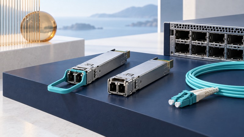
Choose a pluggable transceiver as part of a complete link. The module must work in the host port, transmit and receive the correct optical signals, and tolerate the loss and power levels of the installed fiber path. A connector that fits answers only the mechanical question.
Start with the exact devices and software at both ends. Keep a record of module order codes, port configuration and the fiber route before changing equipment. That record makes both selection and fault finding much more efficient.
Check five kinds of compatibility
On a narrow screen, scroll the table horizontally. Keyboard users can focus the table region and use the arrow keys.
| Layer | What to match | Common missing detail |
|---|---|---|
| Host | Exact switch/router, line card, port, software and supported module. | A familiar form factor can have unsupported variants. |
| Electrical/link mode | Rate, lane arrangement, modulation and required FEC or port mode. | A speed label alone may omit the required configuration. |
| Optical interface | Standard, transmit/receive wavelengths and permitted power levels. | Bidirectional single-fiber pairs may require complementary wavelengths. |
| Fiber path | Single-mode/multimode type, grade, length, connectors and polarity. | Duplex or parallel-fiber wiring must connect the intended transmit and receive paths. |
| Operation | Module power, temperature, airflow and diagnostic support. | A supported port can still face thermal or environmental constraints. |
Use the host vendor’s current compatibility matrix and the exact module data sheet. Cisco’s Optics-to-Device Compatibility Matrix is an example of the necessary lookup. Document both ends; approval for one host does not establish support in the other.
Match the optical specification rather than casing color or a vendor nickname. For bidirectional modules, explicitly pair the transmit wavelength at one end with the receive wavelength at the other. Preserve the fiber’s polarity through patch panels.
Check both weak-signal and overload limits
For a simple compatible optical link, available loss budget is minimum transmitter output minus receiver sensitivity, using comparable specifications in dBm. The resulting difference is in dB. Subtract worst-case fiber, connector, splice and other specified penalties, then retain the design reserve required by the application.
Juniper’s fiber-budget method uses worst-case transmitter and receiver values. Some optical specifications use optical modulation amplitude or additional dispersion penalties; follow the relevant standard and data sheets rather than mixing unlike quantities.
All values above are fictional. An attenuator, if appropriate and approved for the actual link, also consumes weak-signal margin. In this example, adding a nominal 3 dB would leave only 1 dB above sensitivity before its tolerance or other penalties; a required 2 dB reserve would then fail. Recalculate both directions and both extremes.
Use diagnostics as clues with conditions
Digital optical monitoring can report temperature, supply voltage, laser bias and optical power where supported. Save readings from both ends with their warning/alarm thresholds, time and interface state. A reading taken after a transient has passed may look ordinary.
Cisco’s ASR 900 monitoring documentation shows that support and monitoring behavior are platform-specific. Consult the guide for the actual host rather than assuming every module reports every parameter.
An alarm threshold is a diagnostic limit supplied by the module or host. Keep it distinct from the optical specification’s guaranteed receiver sensitivity and overload limit. Sensor accuracy, calibration and implementation can also affect readings; questionable telemetry may require a suitable external optical measurement.
Investigate a failed or intermittent link
- Record the symptom: never comes up, drops intermittently, or carries traffic with errors. Preserve counters, logs and both endpoints’ configuration before resets erase evidence.
- Confirm host support, correct port mode, speed/FEC requirements and module identity. Verify the remote port is enabled and configured consistently.
- Trace the actual fiber route, type and polarity, including patch-panel changes. Follow the equipment’s fiber handling and connector inspection/cleaning procedure; never look into an optical port or fiber end.
- Compare transmit and receive diagnostics at both ends with the module’s specifications and thresholds. Distinguish one-way from two-way problems.
- During an approved maintenance interval, substitute one known-compatible element at a time, such as a patch lead or module. Preserve the same remaining configuration.
- Repeat under representative traffic and environmental conditions, then record whether the fault follows the module, fiber path or host port.
Cisco’s Catalyst 9000 fiber troubleshooting guide connects compatibility, polarity and optical readings with common symptoms. Commands and feature availability in that guide apply to its documented platforms.
Keep a link record that survives a replacement
Label the two endpoints and the fiber route. Store the module order codes, firmware/software, compatibility evidence, calculated margins and a normal diagnostic snapshot. Add the date and reason whenever a module or patch lead changes.
The worksheet has separate fields for minimum and maximum loss, sensitivity and overload. Keeping both calculations visible prevents “more optical power” from becoming the default response to a link problem.
Keep a working record
Download the pluggable transceivers worksheet (editable text). Save a copy for each comparison or test. It includes the example assumptions, fields for source references and space for your results.